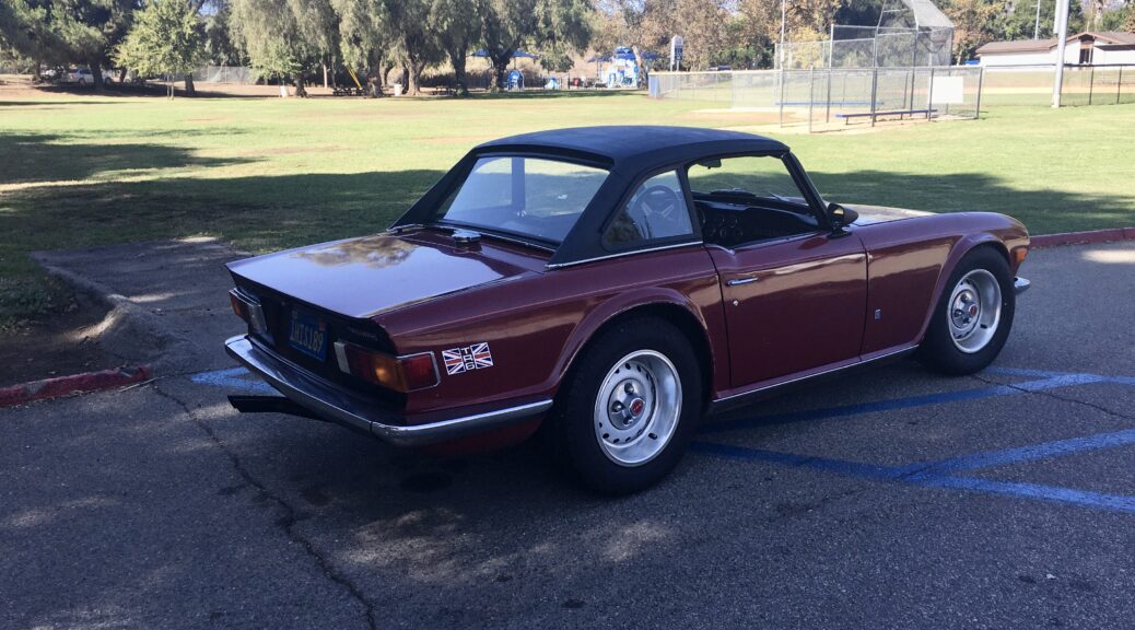
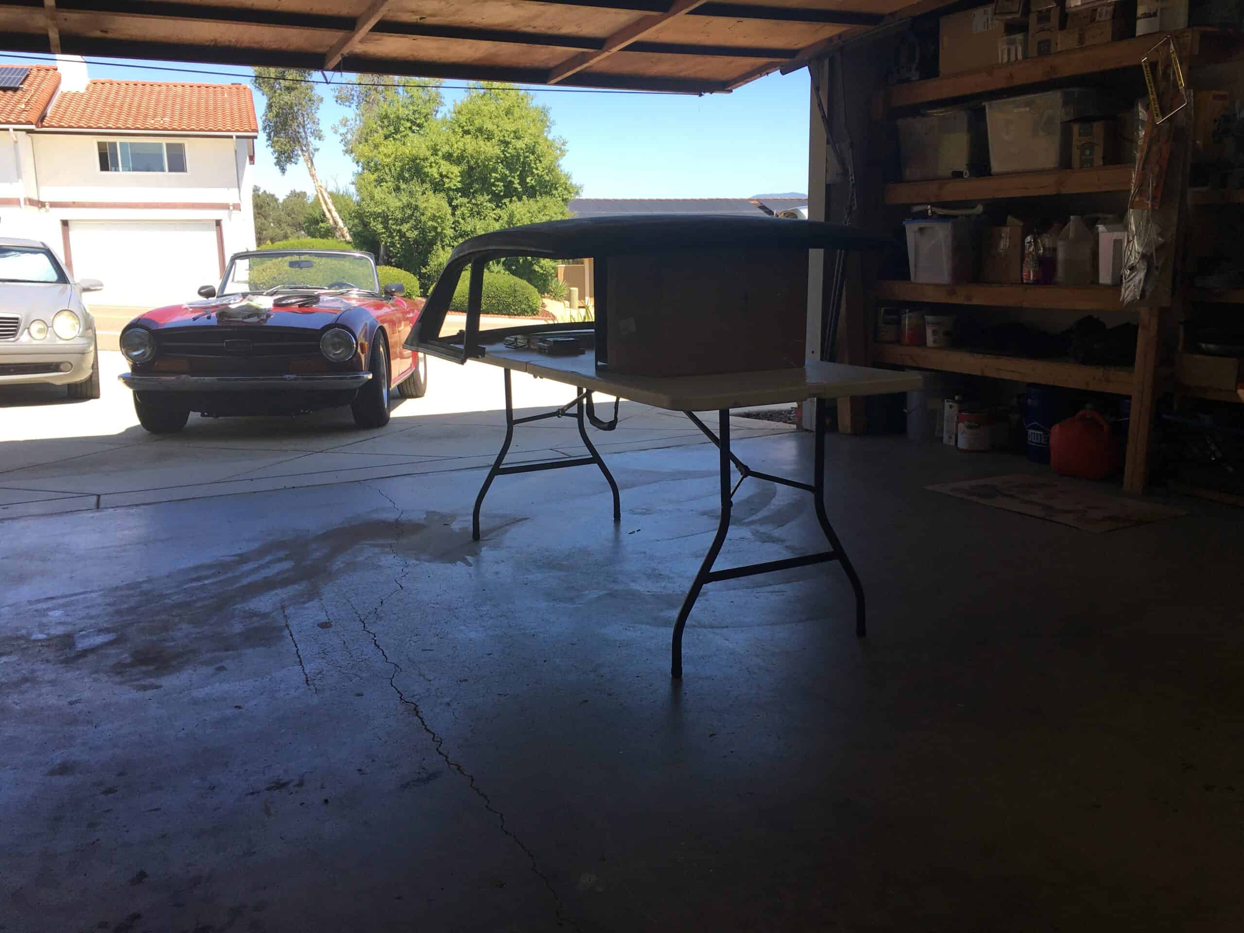
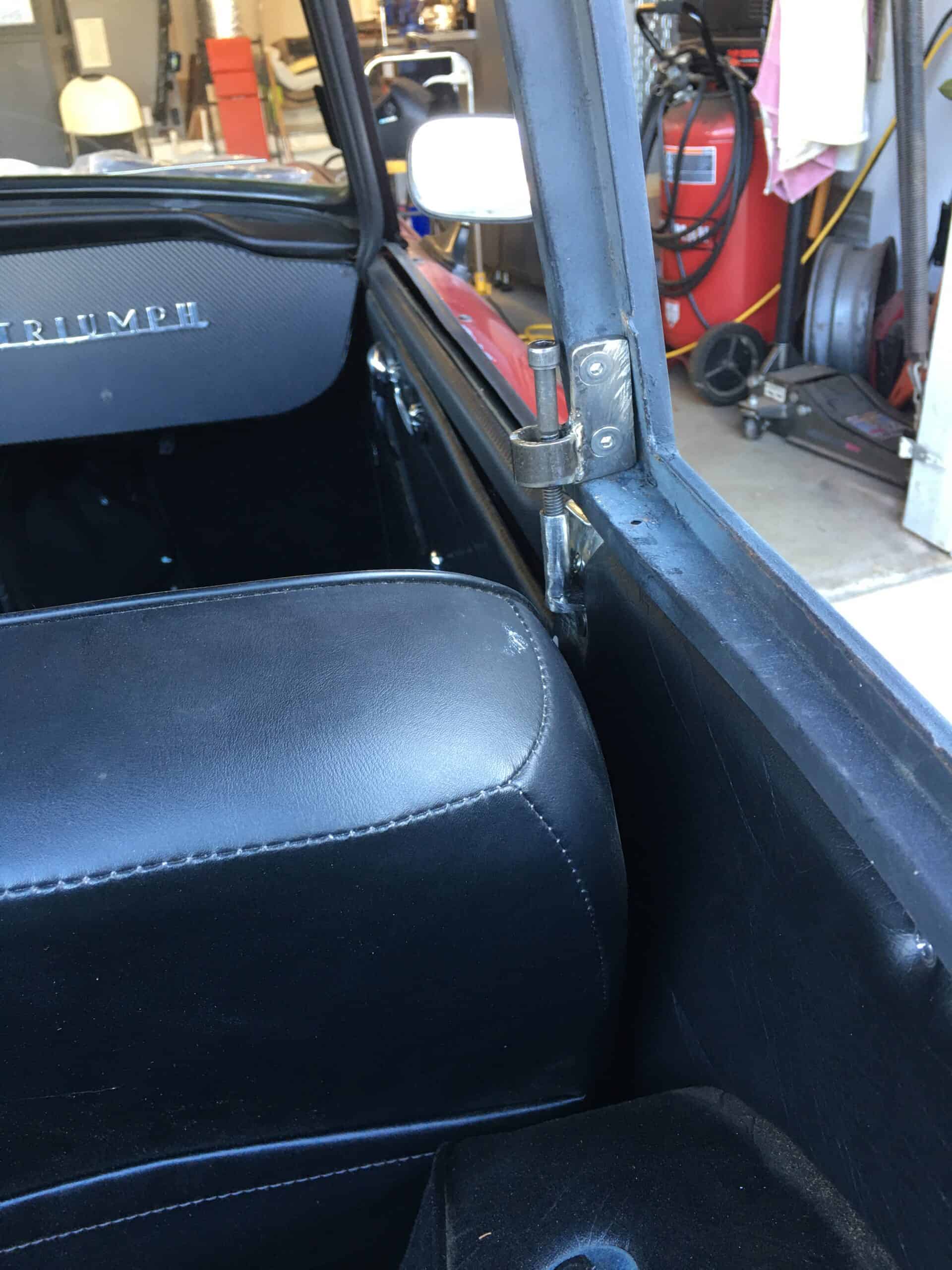
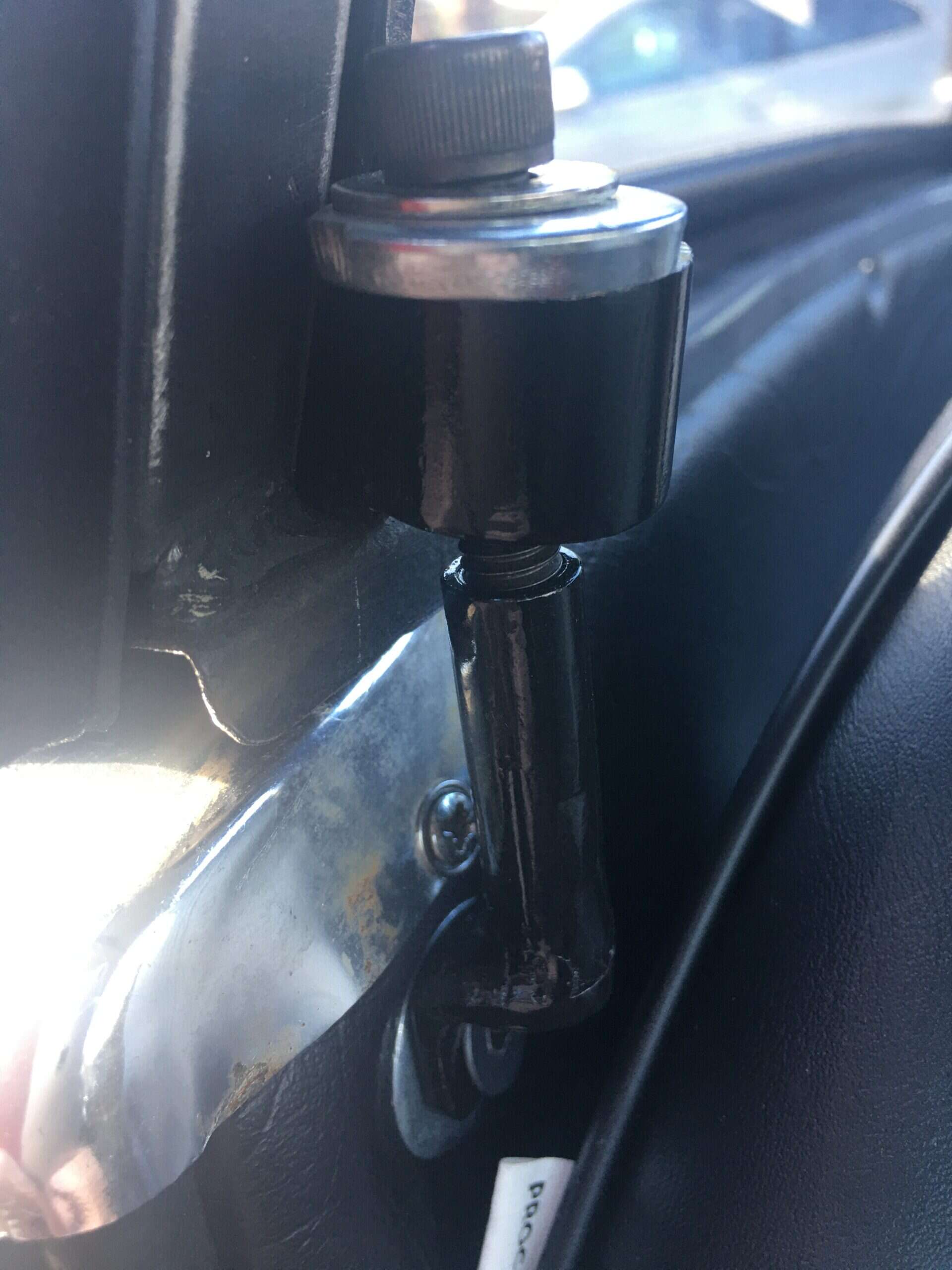
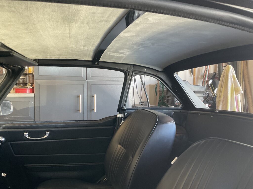
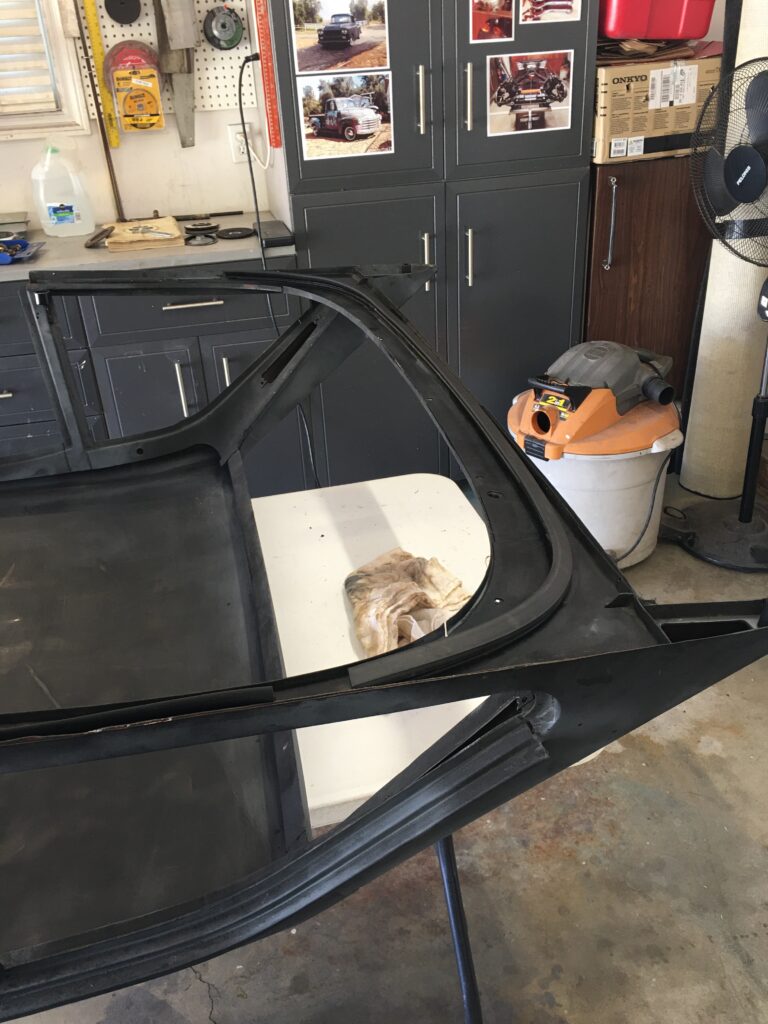
I have been half-heartedly looking for a factory hardtop for the Six, and this summer I lucked out and found one within an hour drive. It was a bare top but included all windows – in excellent shape – and some but not all of the rubber. The paint looks like rattle-can flat black and there are a couple very slight dents front and center, hardly noticeable now but which would need fixing prior to painting. I had to make the mounting brackets at the B-pillar, and I added insulation and headliner, as shown in the photos.
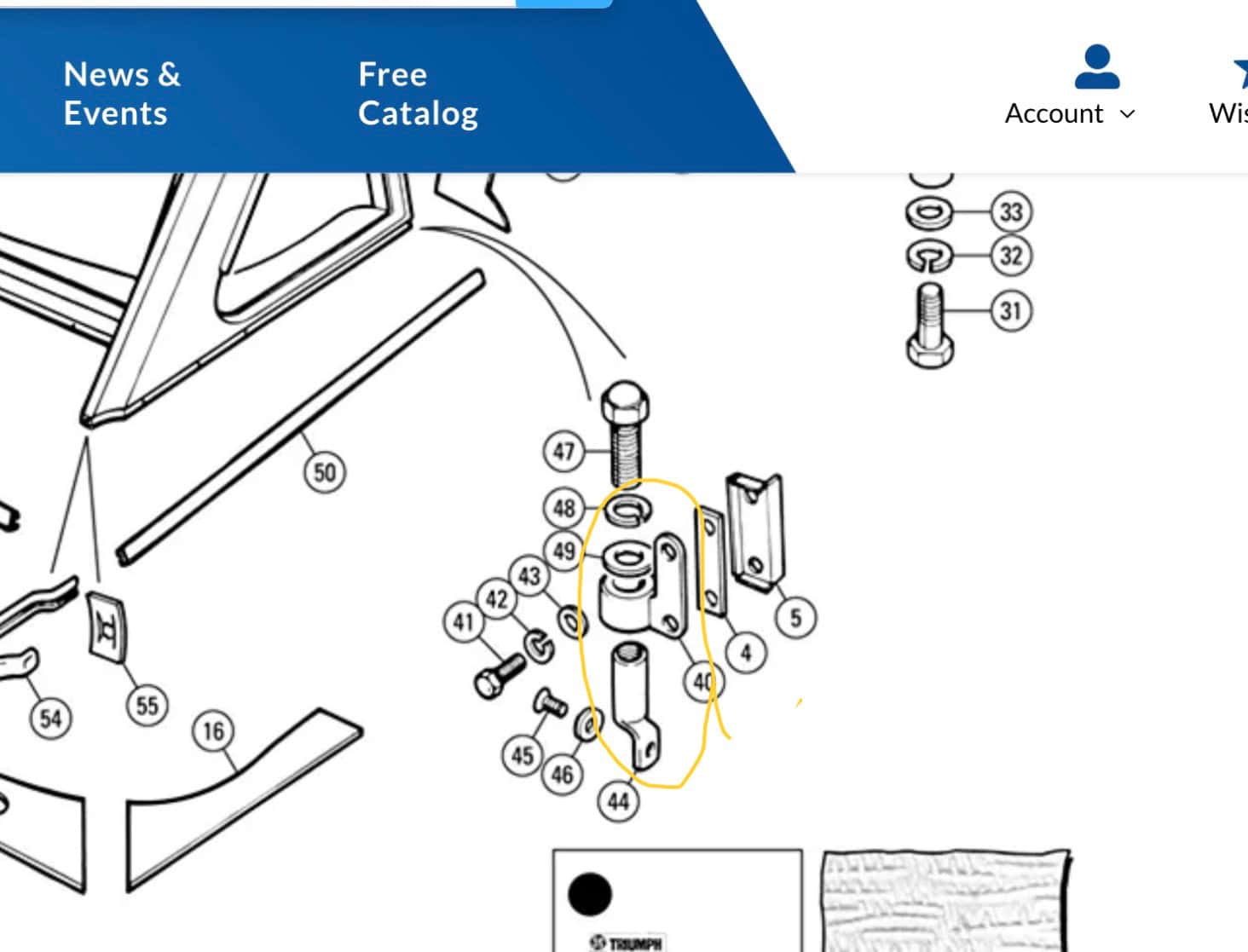
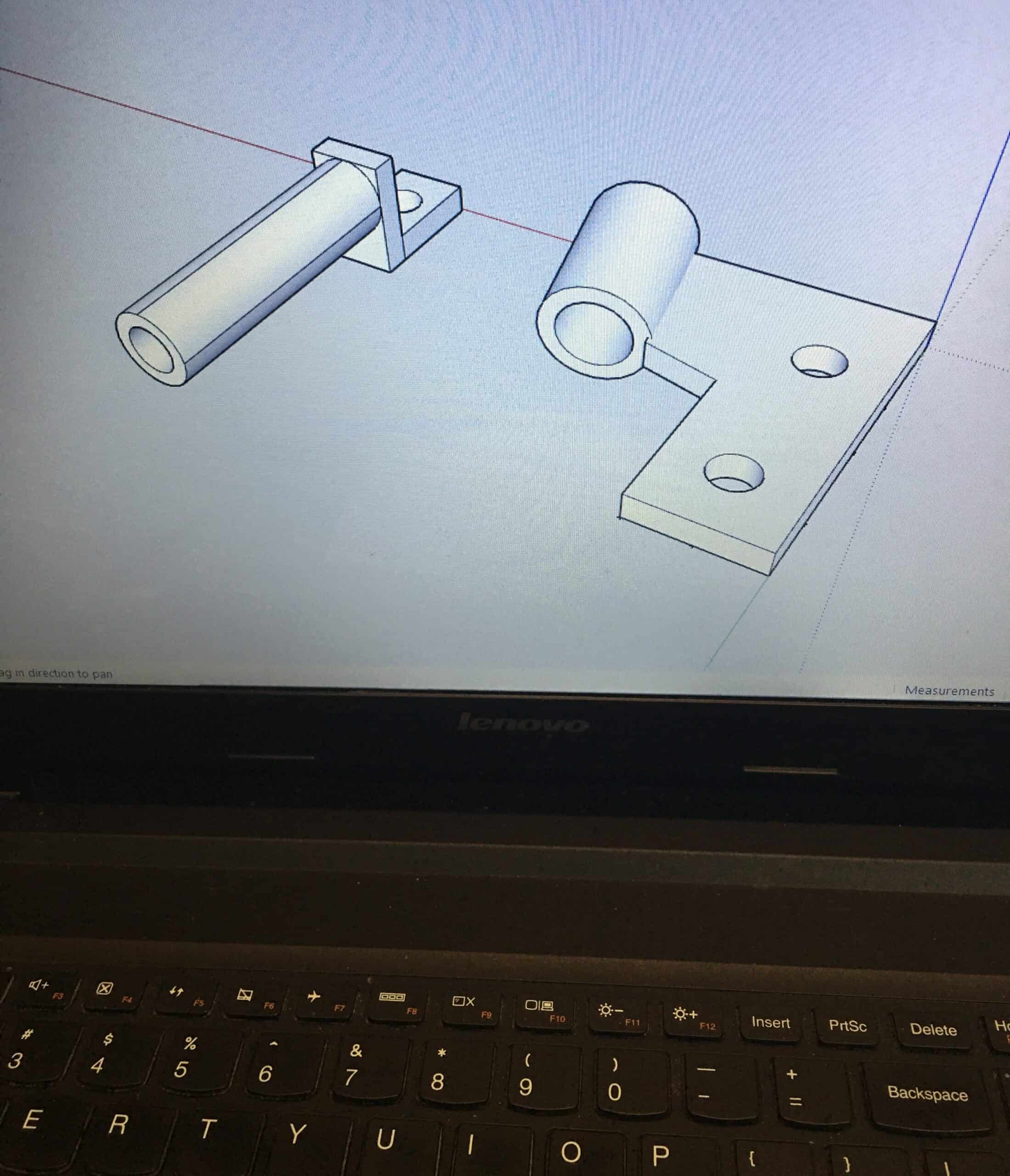
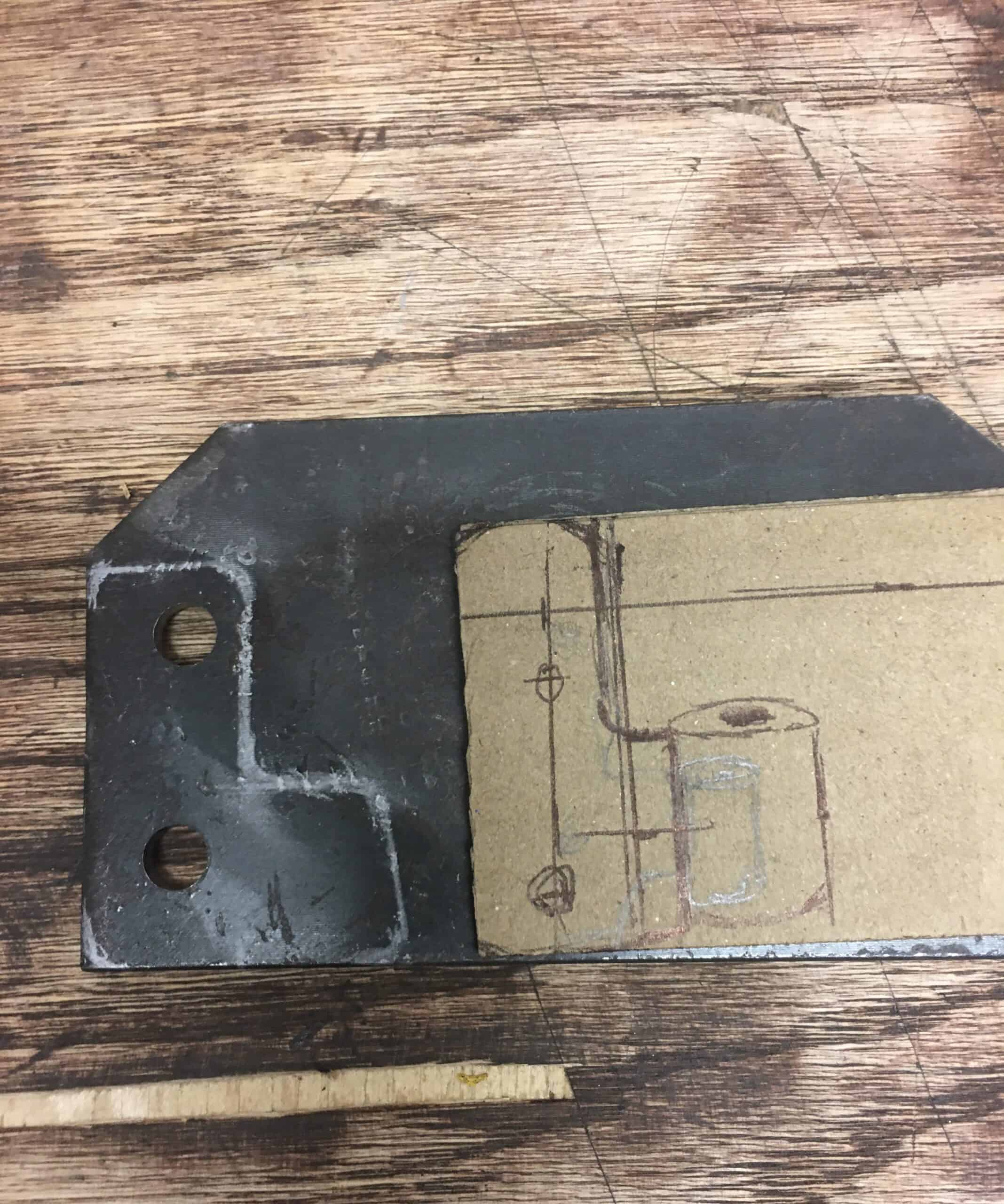
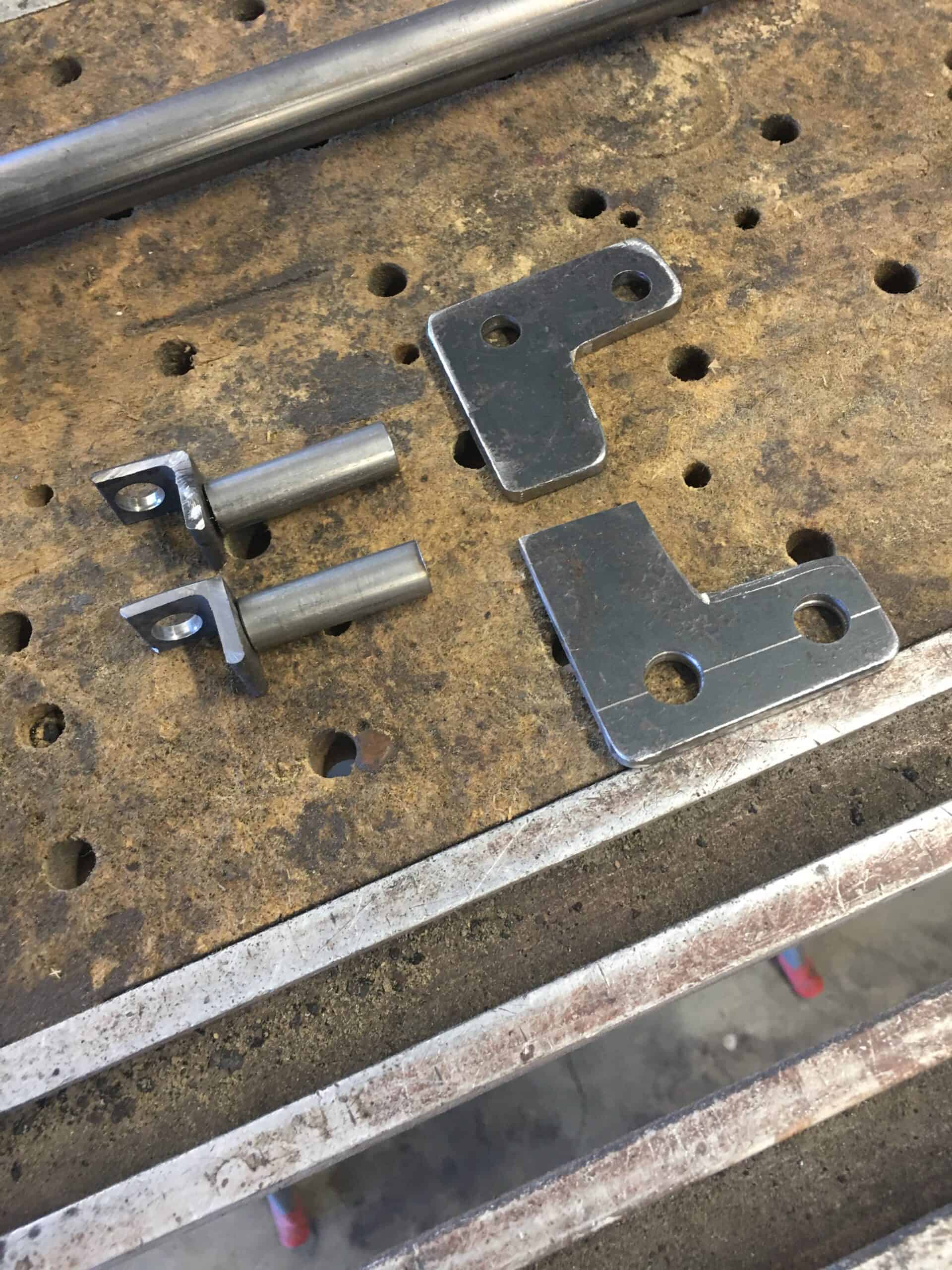
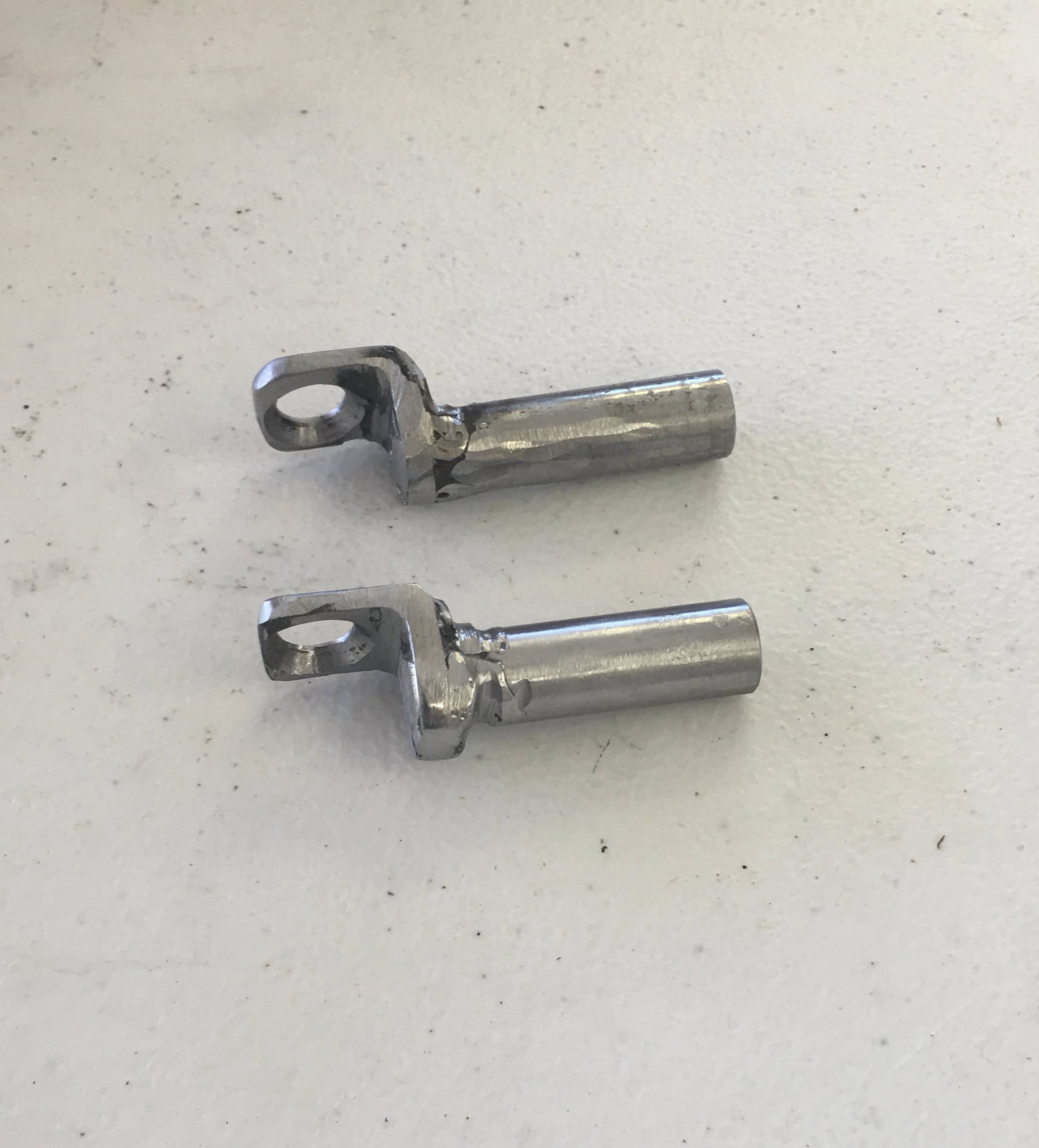
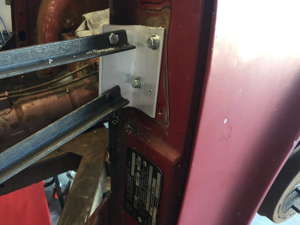
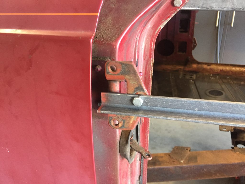
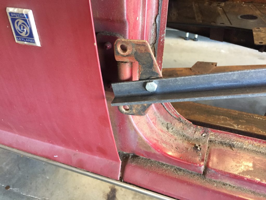
First, I made the B post brackets, which were either unavailable or crazy expensive.
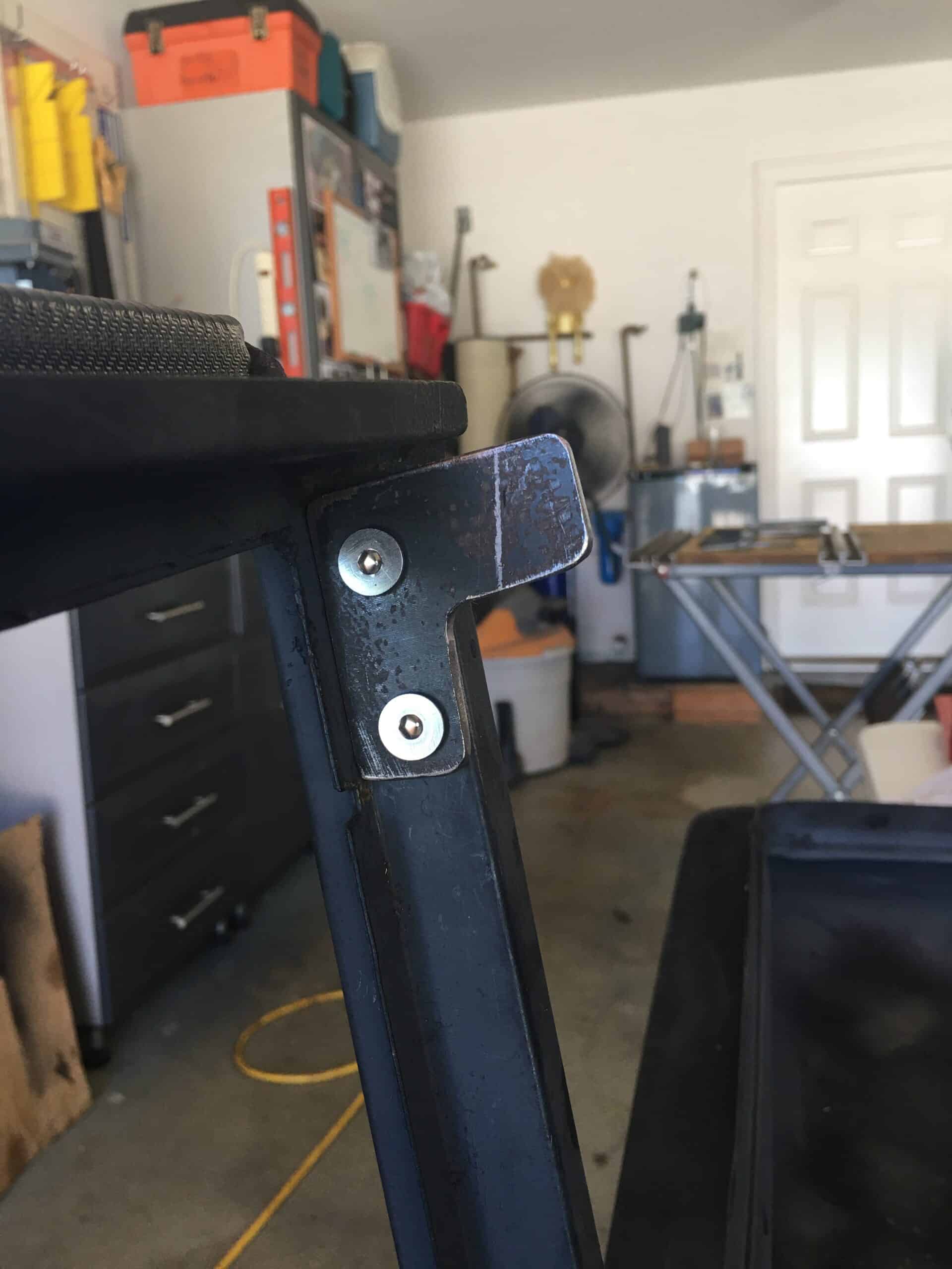
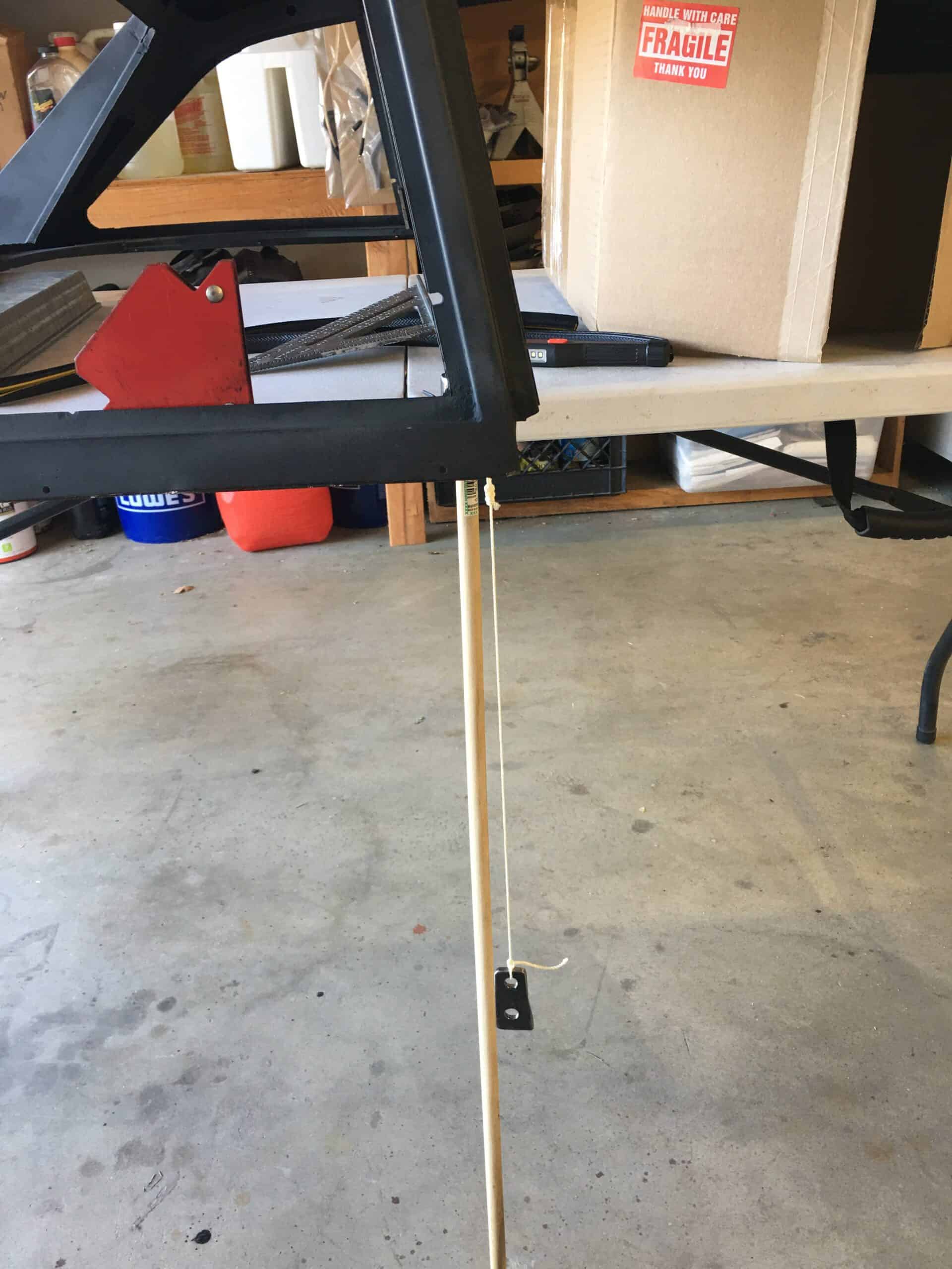
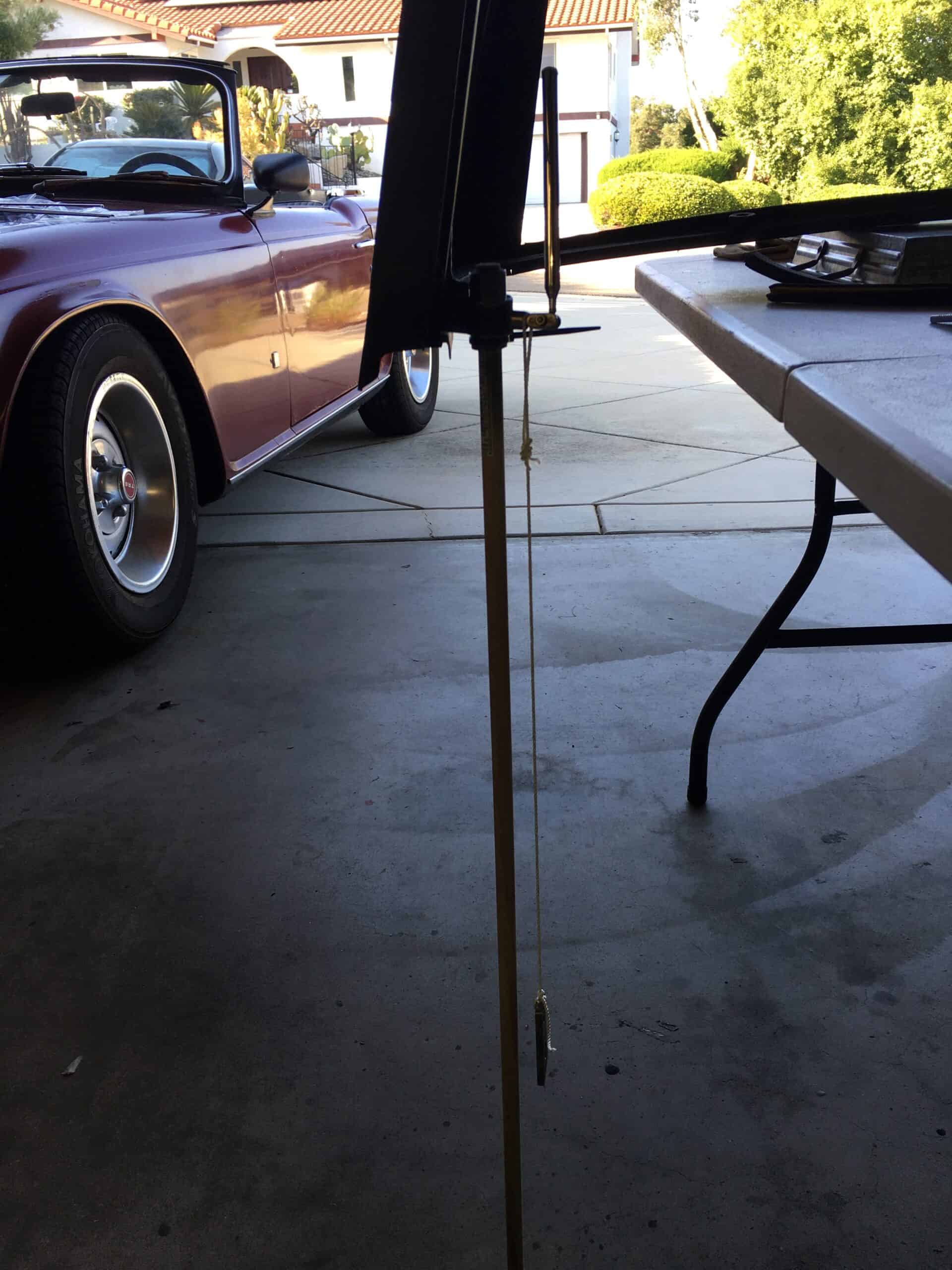
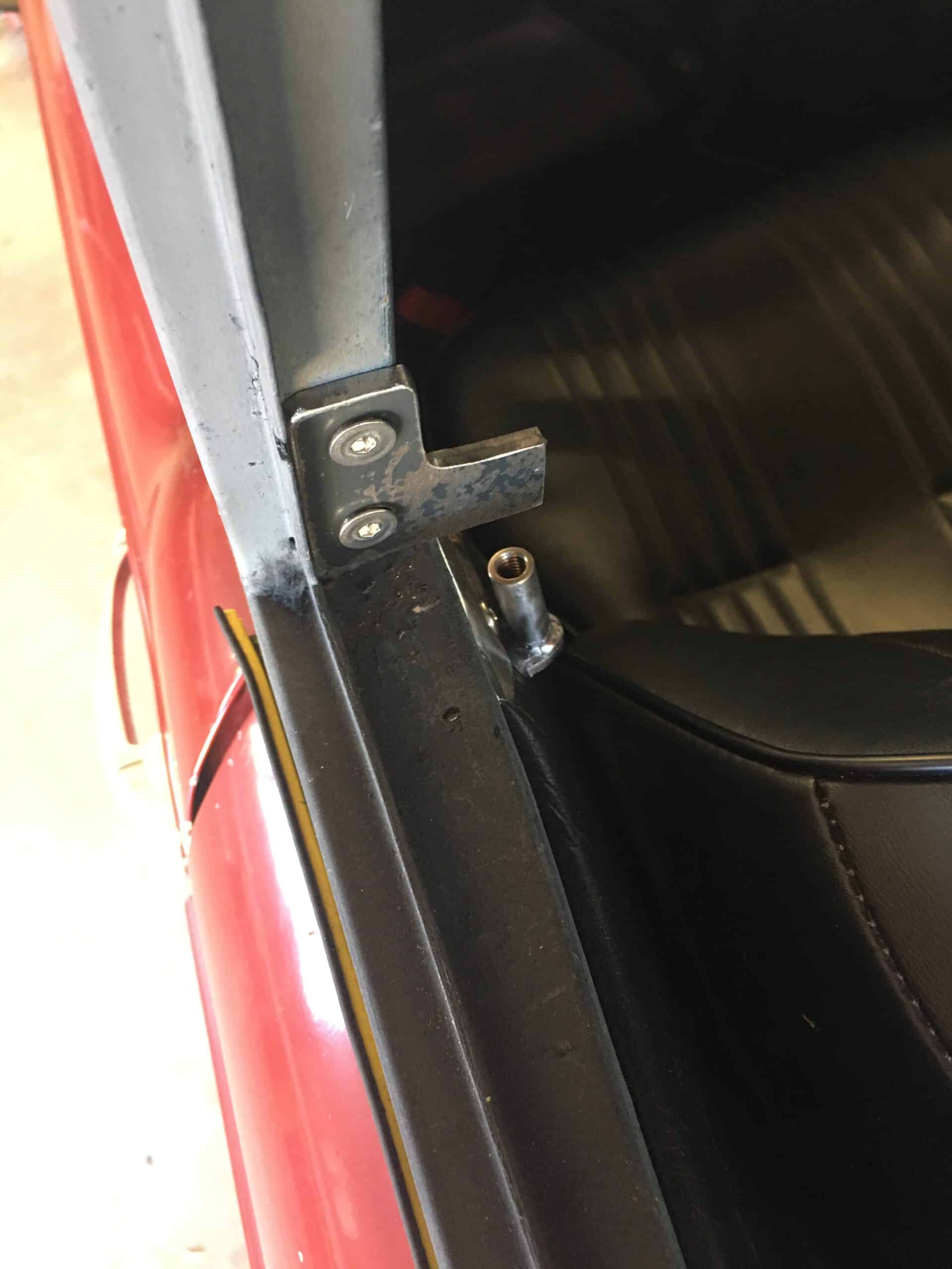
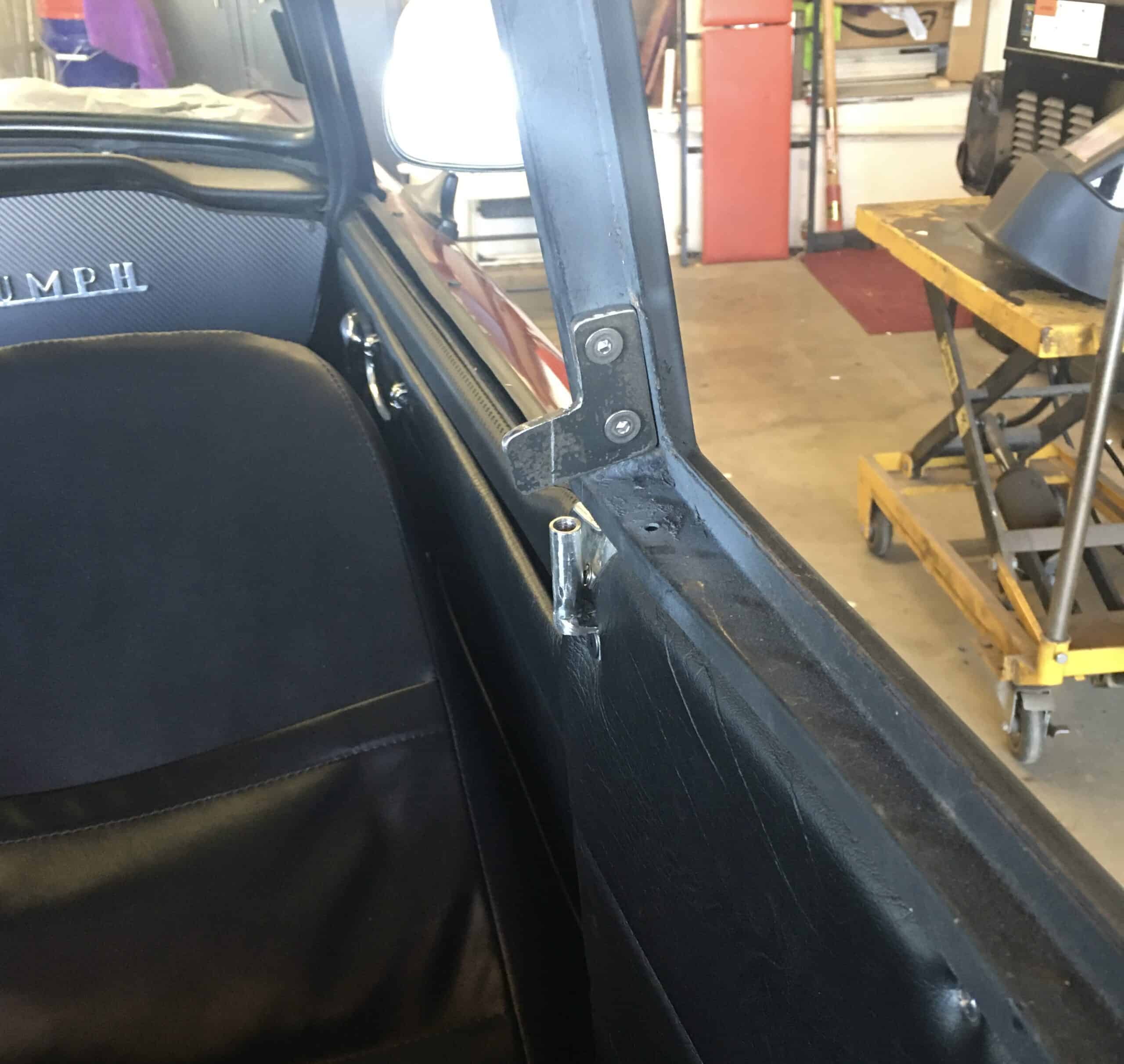
B post brackets were unobtaniumSketchUp to visualize what I needed to makeTime to cut some metal, 3/16th steelAngle iron, internally threaded tube, and the 3/16th platesWelds are a bit rough because I didn’t use our gas shielded rig at the barn, but good enoughTest fittingGetting the top level for the next stepPlumb bobbing, there are two angles to deal with… just trying to get close.The B-post leans toward center of the car and leans toward the rear, so we are plumbobbulating. Your new word for the day.Eye-ballingDrawing lines and eye-balling againA little black paint, a couple washers, and we’re doneFinished B-post bracket, not perfectly aligned, but the top is easy to install and it’s not going to fly off
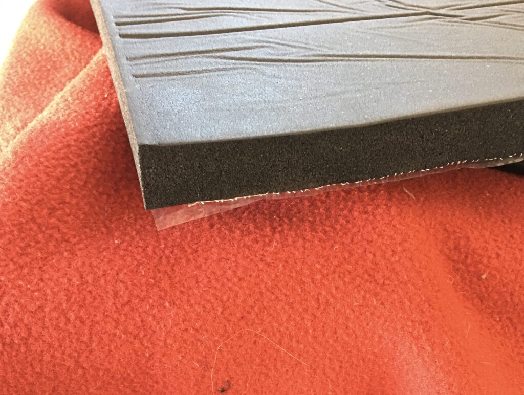
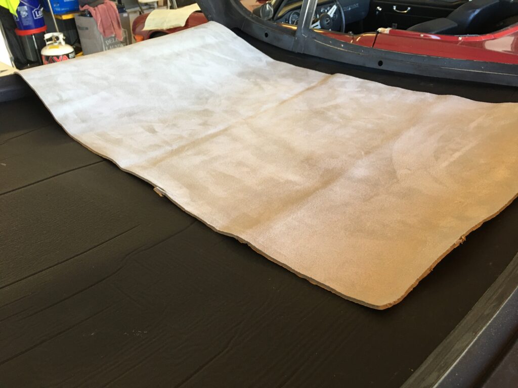
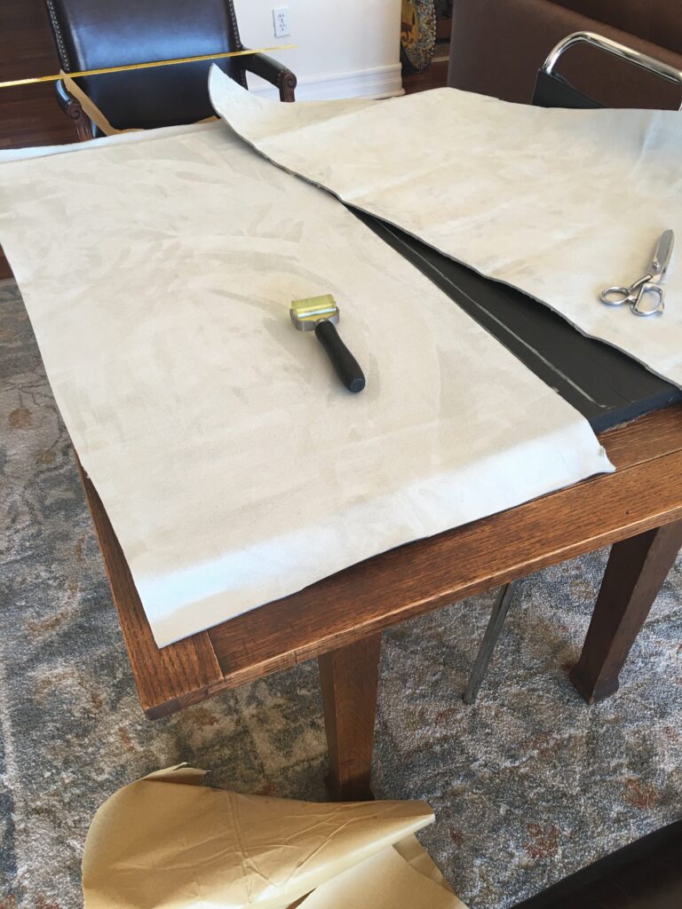
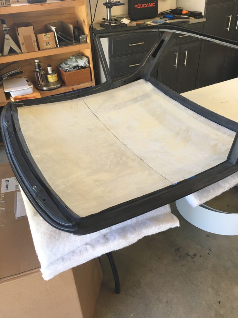
Although I’m not finishing the top at this time, I did want to experience enclosed driving through the winter, and decided to try and make it quiet with insulation and headliner.
Adhesive backed 3/4 inch foamNice soft suede, 1/4 inch foam, also adhesive backedTest fitting the insulationGetting set to cut the headliner to fit the 3/4 insulationThe suede headliner I selected required a two-piece approachAll stuck togetherMetal rib covers the seamNot a bad result, with a total of an inch insulation, around $100 for the materials
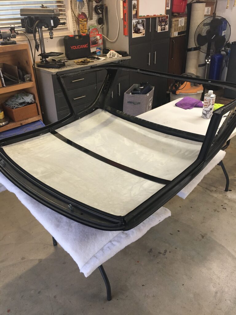
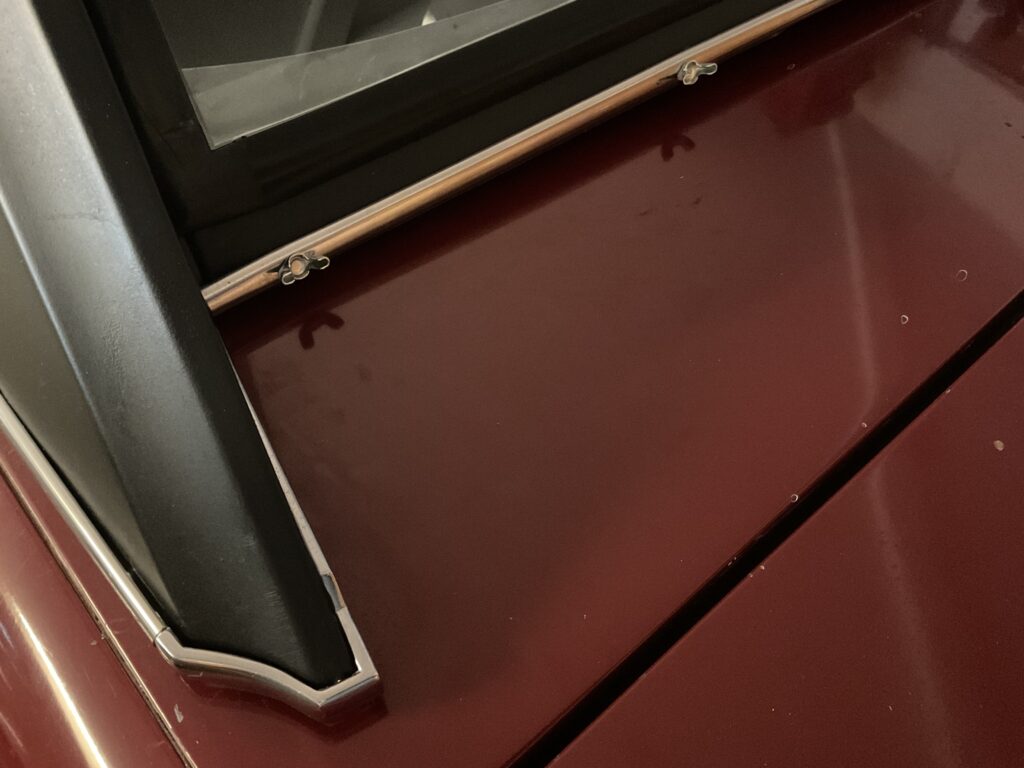
The final steps included installation of the seals, the glass, and the chrome trim. I chose to have the glass done by Grace Auto Glass, as I had used them previously when assembling the windshield a few years ago.
It seemed to me there were some conflicting and incorrect comments re installing the seal between the hardtop and the windshield. So, quoting the official Fitting Instructions for Item 11, the Hardtop to Windshield seal, this is the process I followed…
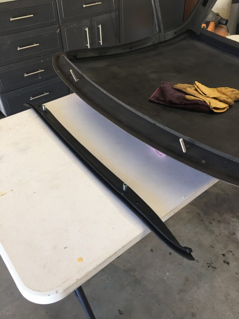
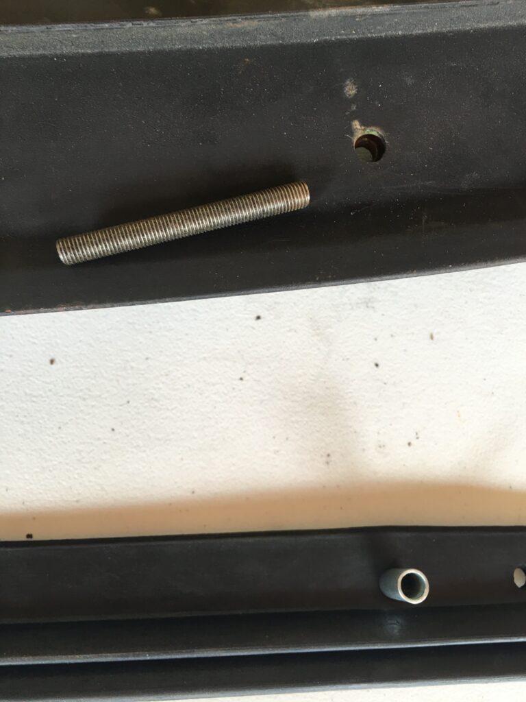
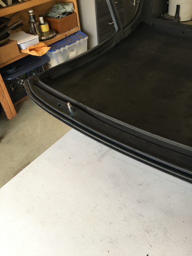
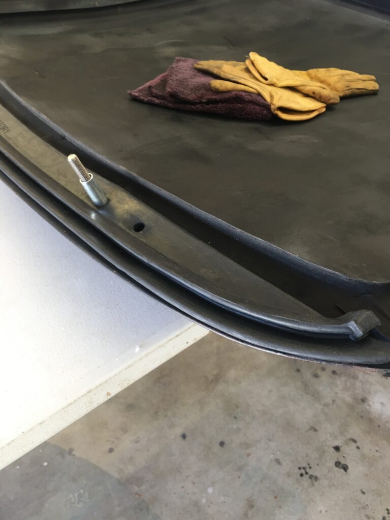
Place the rubber with flat side facing upwards and apply adhesive to the complete area of the flat surface. Insert distance tubes through the inner holes of the rubber. Screw a 5/16 inch “slave” stud finger tight to each of the two weld nuts in the header panel of the Hard Top, in order to locate the exact position of the rubber. Position the rubber to header rail and press down firmly to ensure satisfactory bond. Remove “slave” studs.
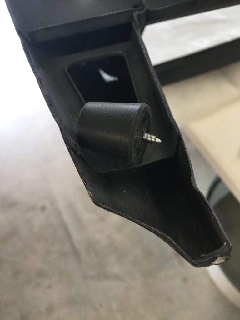
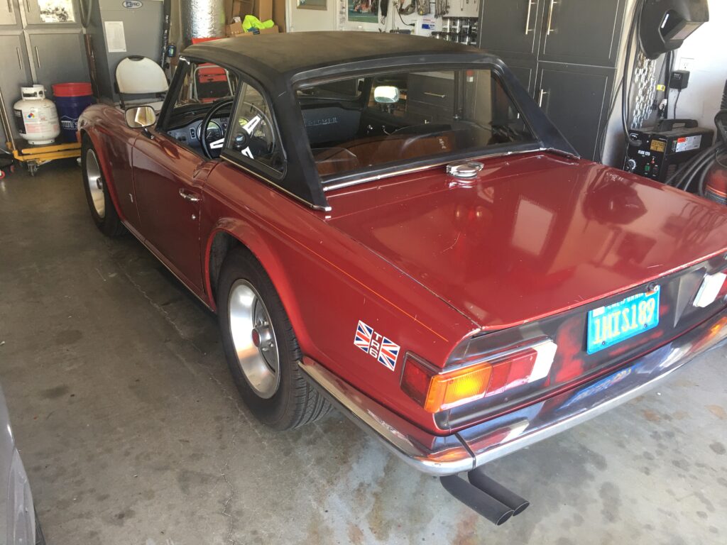
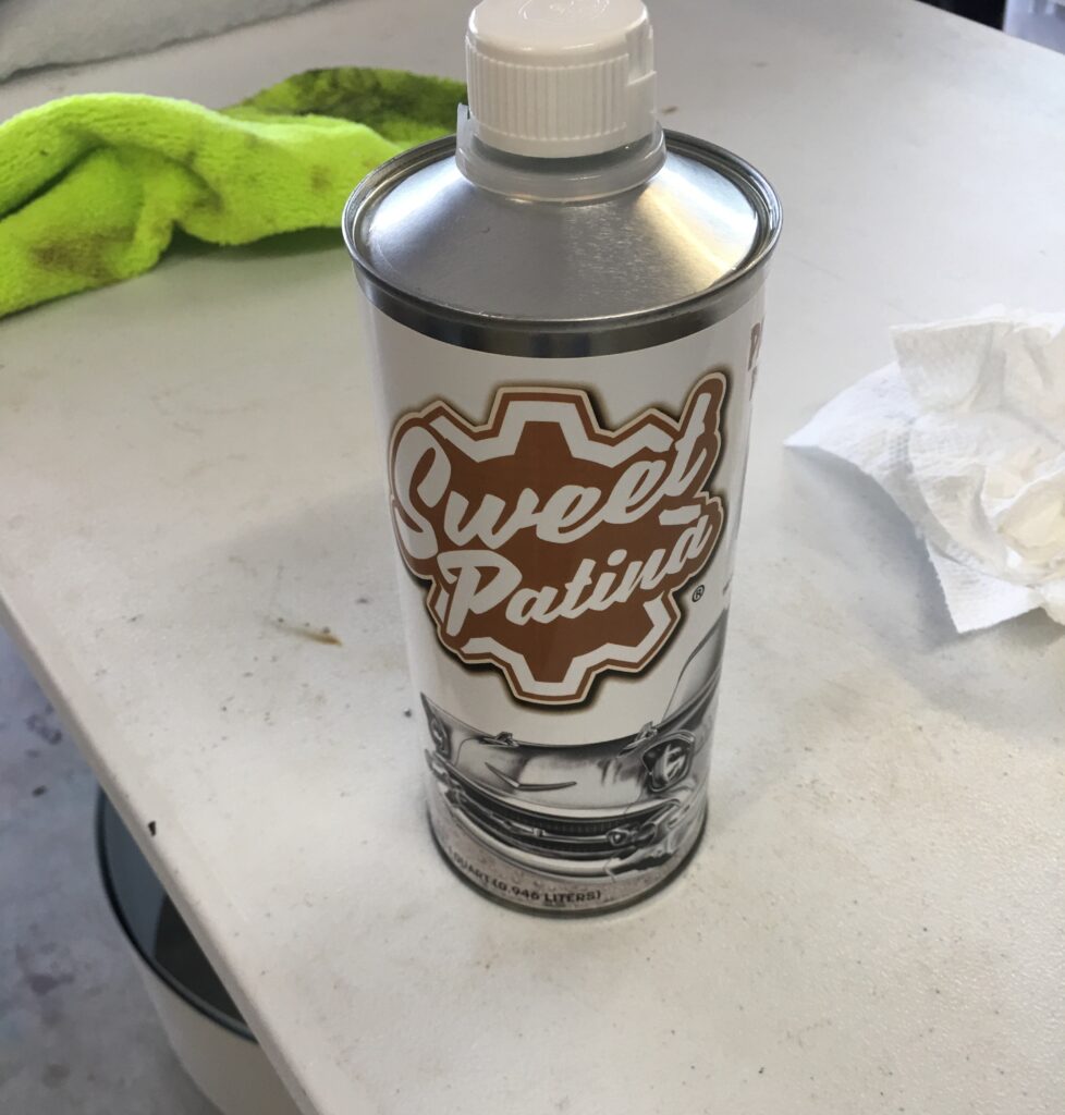
HT to WS seal, studs finger tight into captive nuts, distance pieces inserted through the rubber seal, ready to apply adhesive5/16 – 18 studsGlued, but I did not apply adhesive across the entire seal, just from a few inches inboard of the distance pieces and out to the endsGlued down, and ready to unscrew the “slave” studsThis seal was a bit tricky, but after cleaning up the channel, and slightly opening up the channel around the sweeping 90 degree turn, it slid in pretty easily. I then tightened the channel up a bit with pliersTrip to Ace Hardware for these stoppers that I drilled through to use as the buffers between HT and rear deckInstalled, with glass and chrome!I could not get the long chrome piece to stay on the rivets, so I got creative. Oh wellSince I am holding off on painting the top (and the entire car) I applied Sweet Patina on the top to offer a little protection against the elements this winter.
The Six actually seems like a real car now rather than a toy, but I’m pretty sure that come next spring the hardtop will be coming back off. For now, I will experience cozy comfort through the San Diego “winter.”
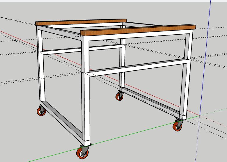
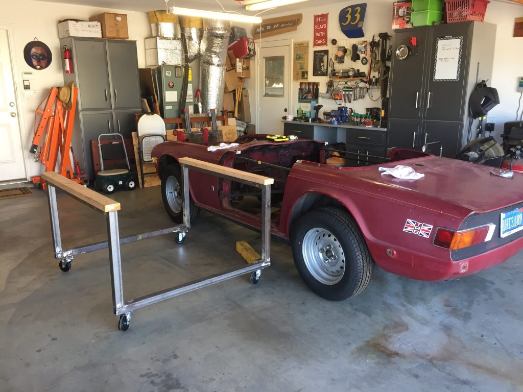
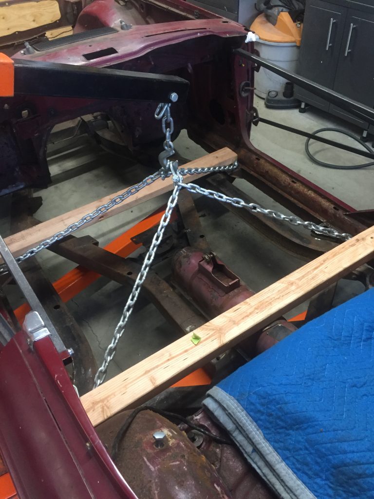
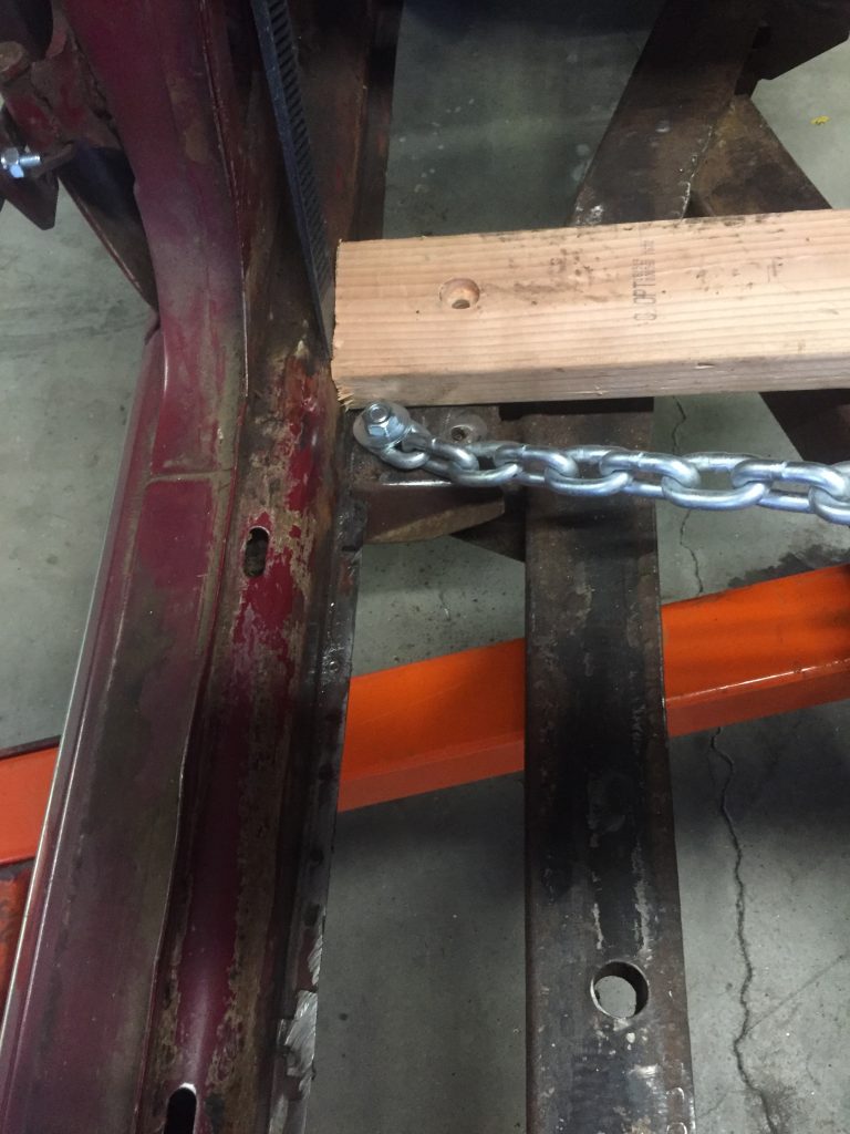
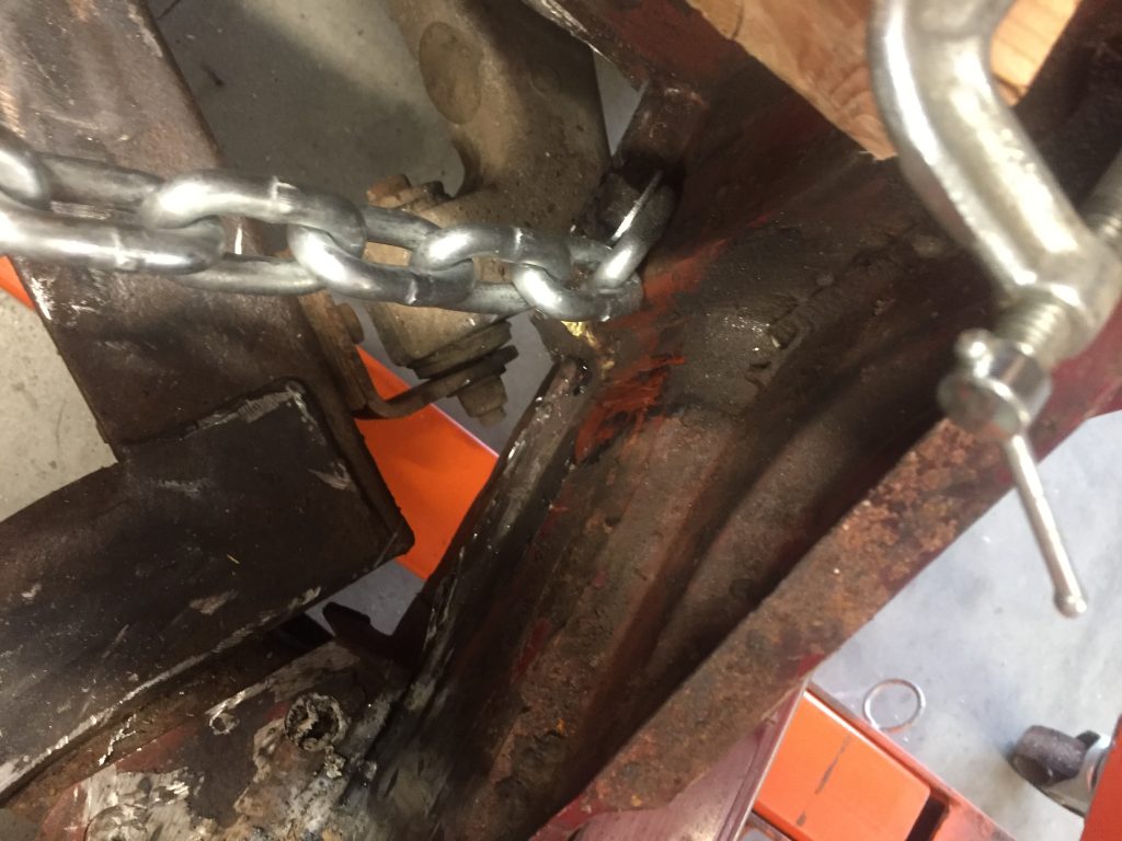
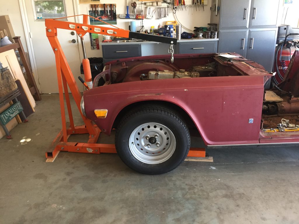
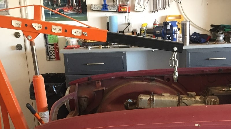
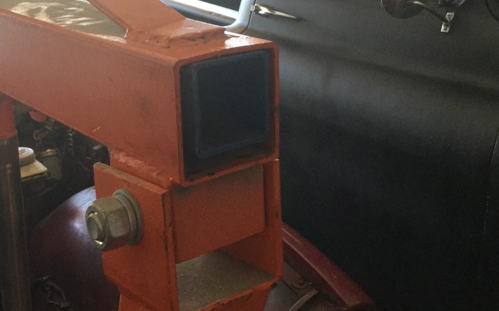
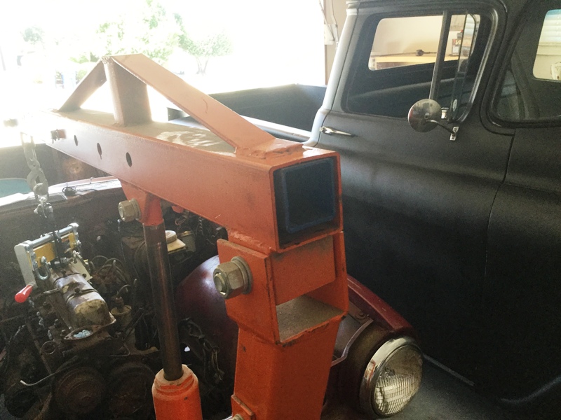
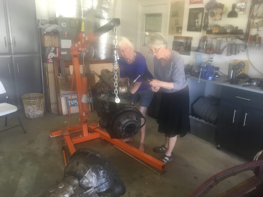
Bringing the leverageI took lots of photos to jog the memory laterDon’t want the body to fold in halfNo new holes or welding in this solutionWhat I envisionedAnd what I ended up buildingFront floor mountsSeat belt threaded holeEngine hoist, wife, and self and it’s off
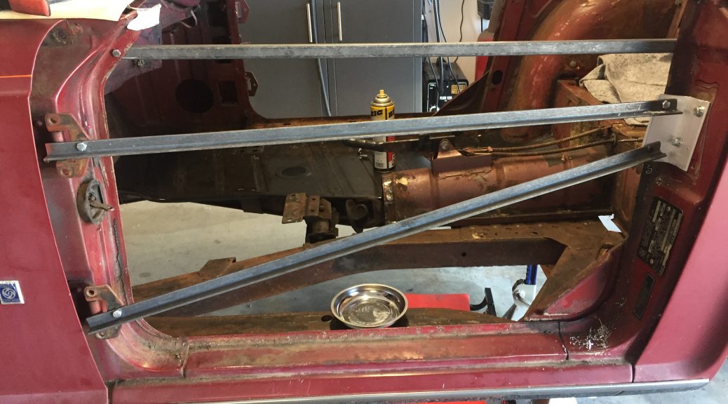
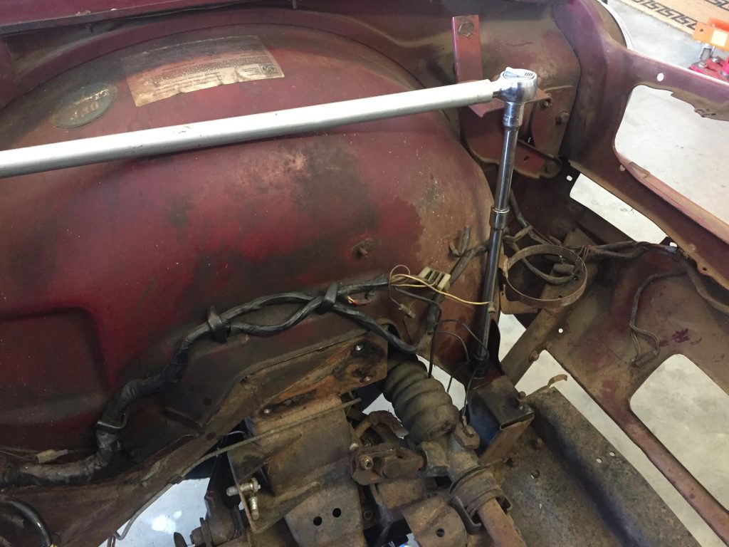
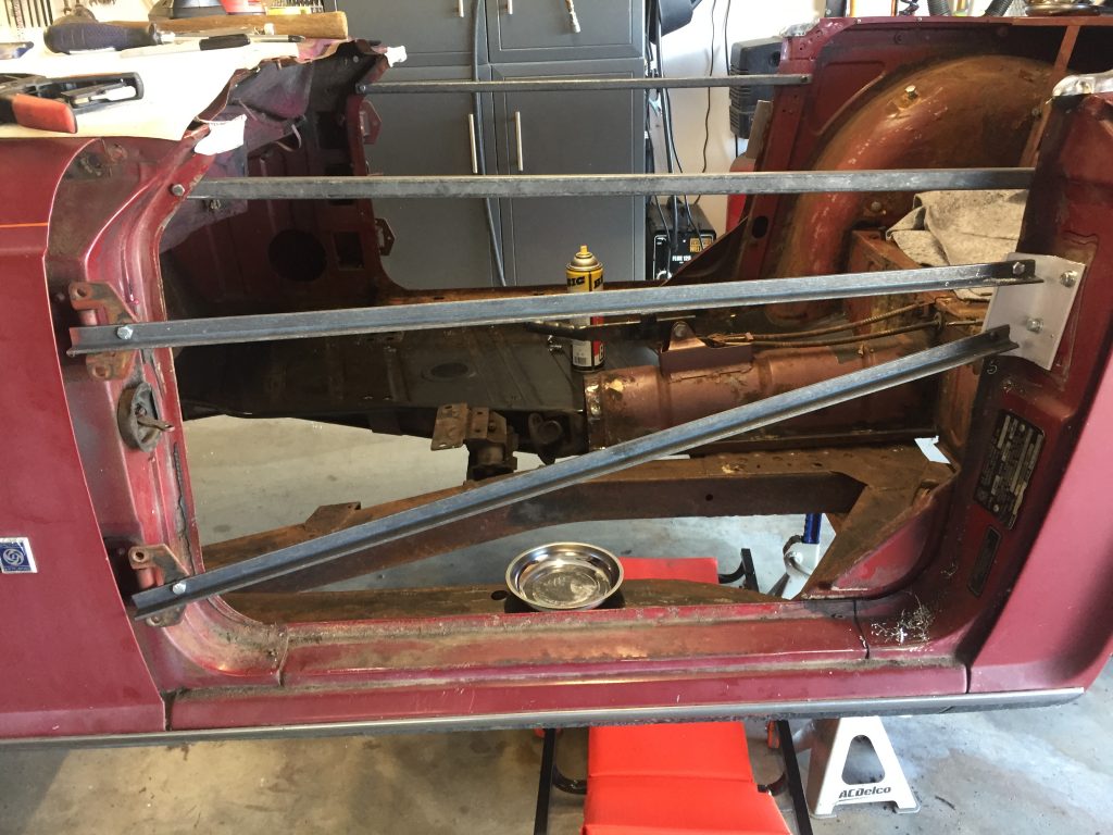
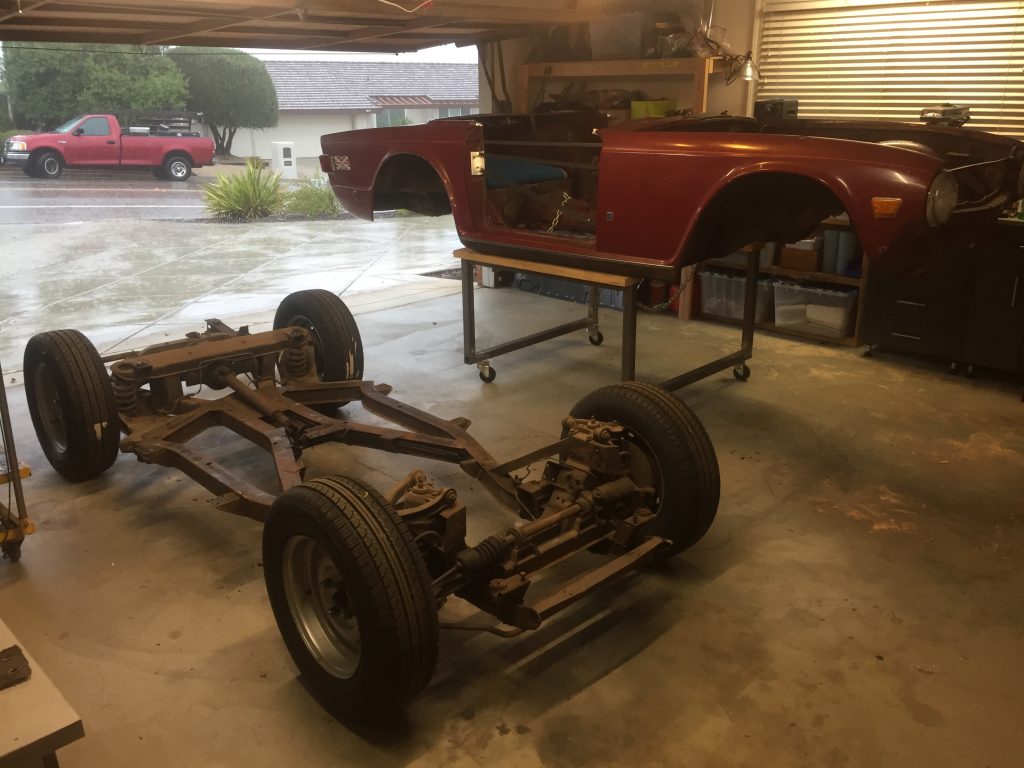
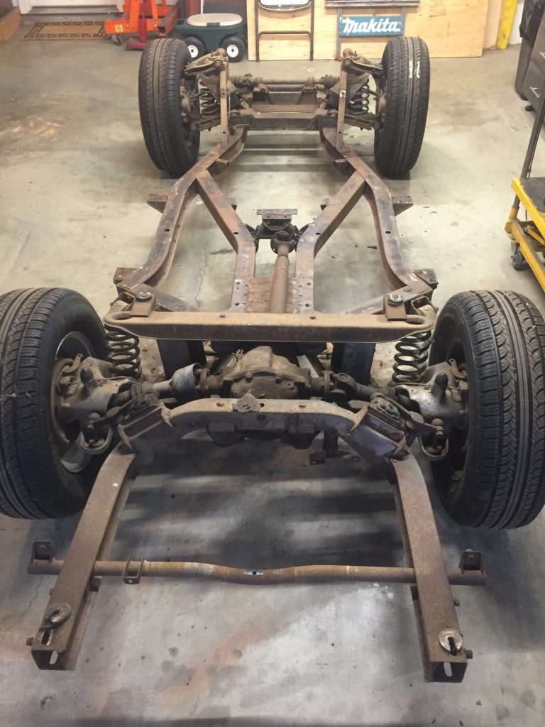
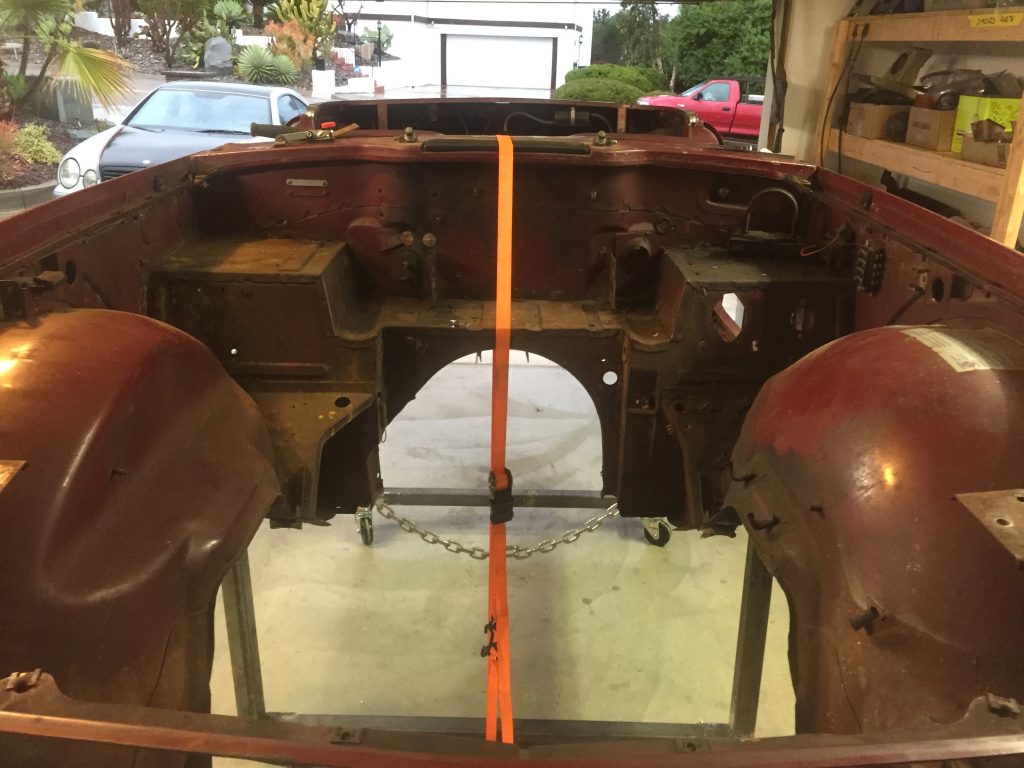
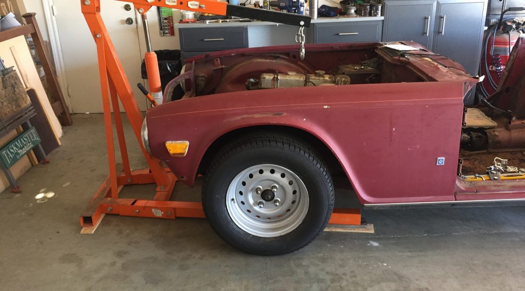
Separating the body from the chassis was a momentous occasion, and pretty straightforward, with the engine and transmission and the passenger floors and gas tank already removed. One of the online sites, can’t remember whether it is TRF or Moss, has a good illustration of all the bolts securing the body, and that was helpful for removal and re-assembly. Of course there are brake lines and fuel lines and other bits that need to be undone, as well.
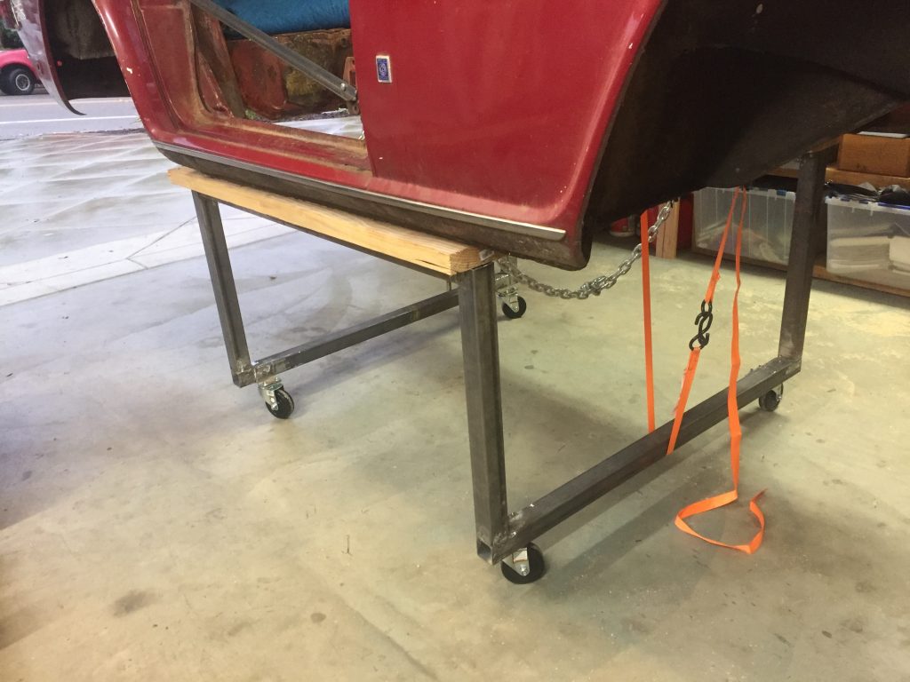
We used our engine hoist to do the lifting, anchoring the chains as shown in the photos. I built a stand with wheels so that the body could be moved around in the garage. The stand also allowed me to work while standing up inside the engine bay or passenger area when necessary. As you can see in the pictures, I utilized the door hinges and latch holes, along with a couple other existing holes, to brace the body so it would not fold and create problems later. I really didn’t want to go to the trouble of welding and and then grinding off the braces, nor did I want to drill any holes.
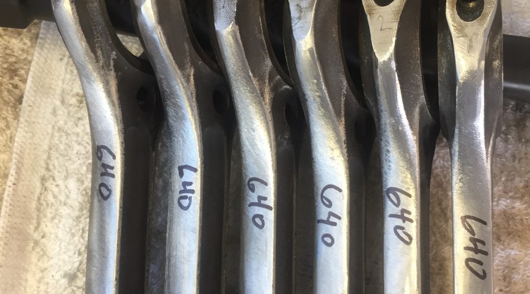
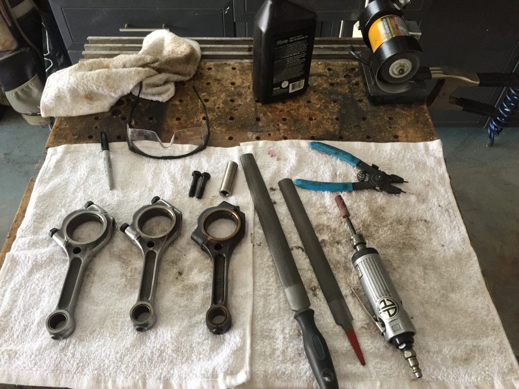
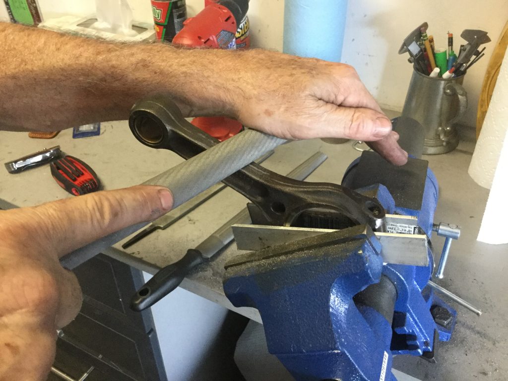
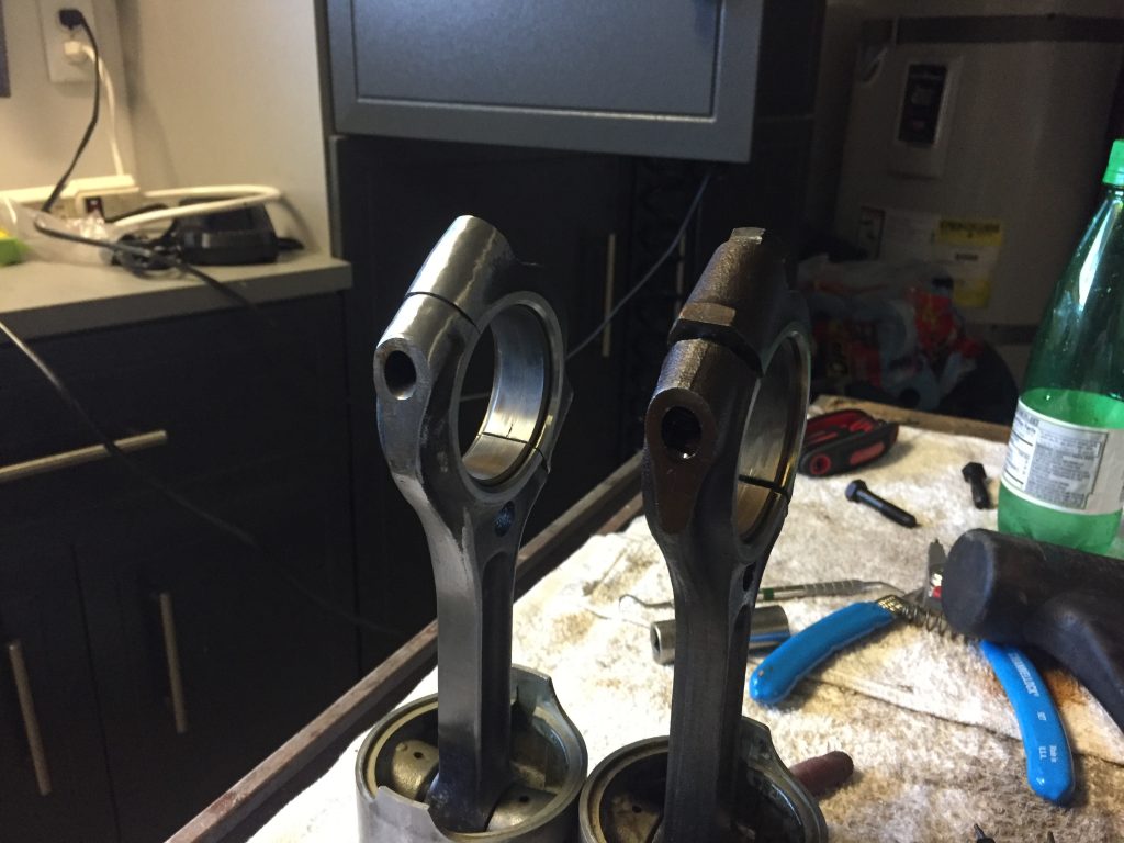
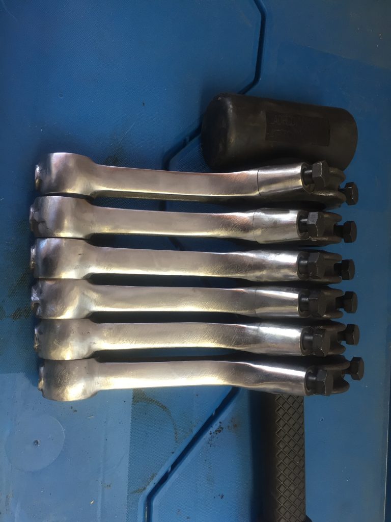
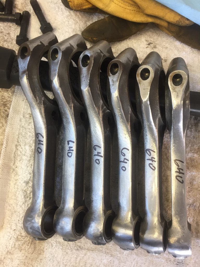
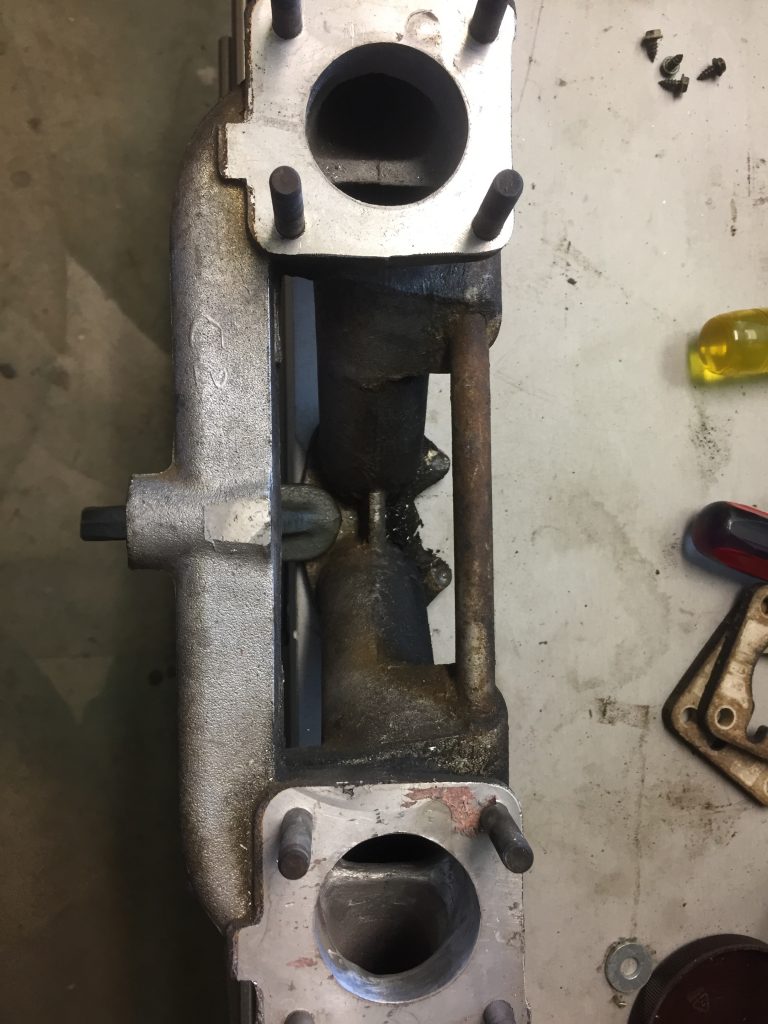
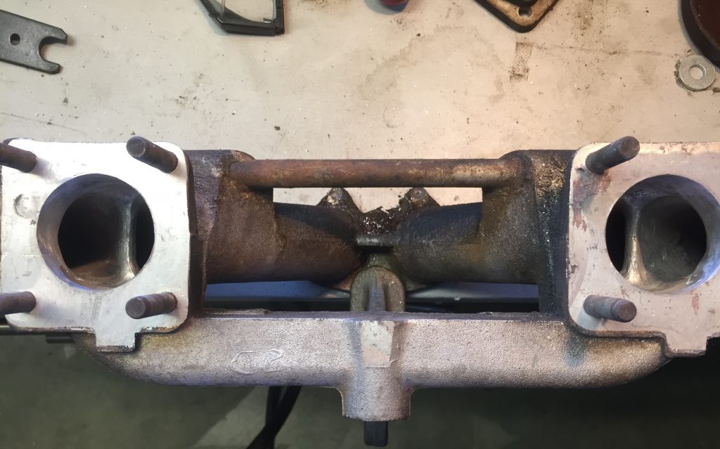
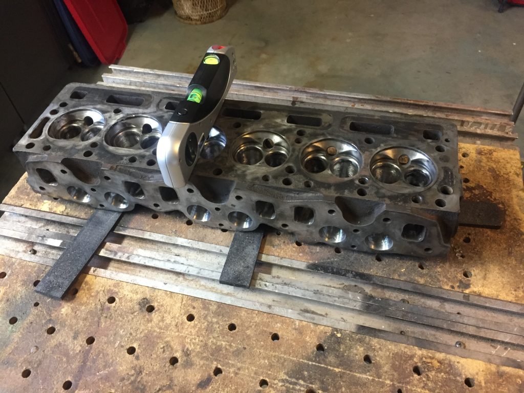
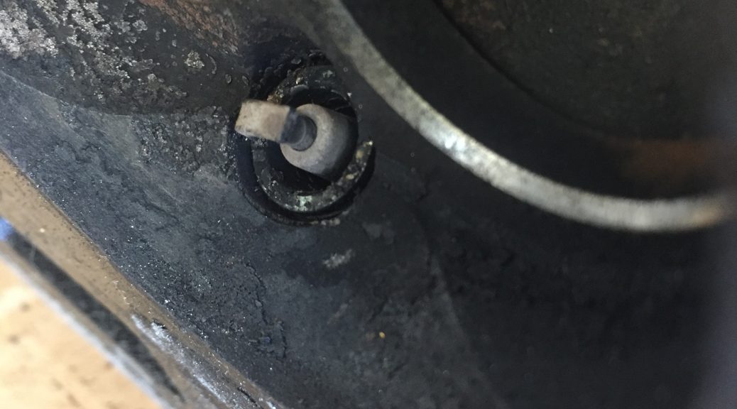
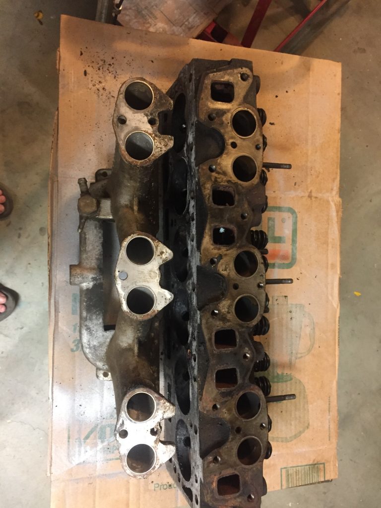
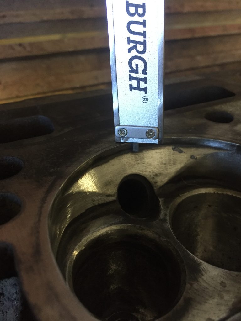
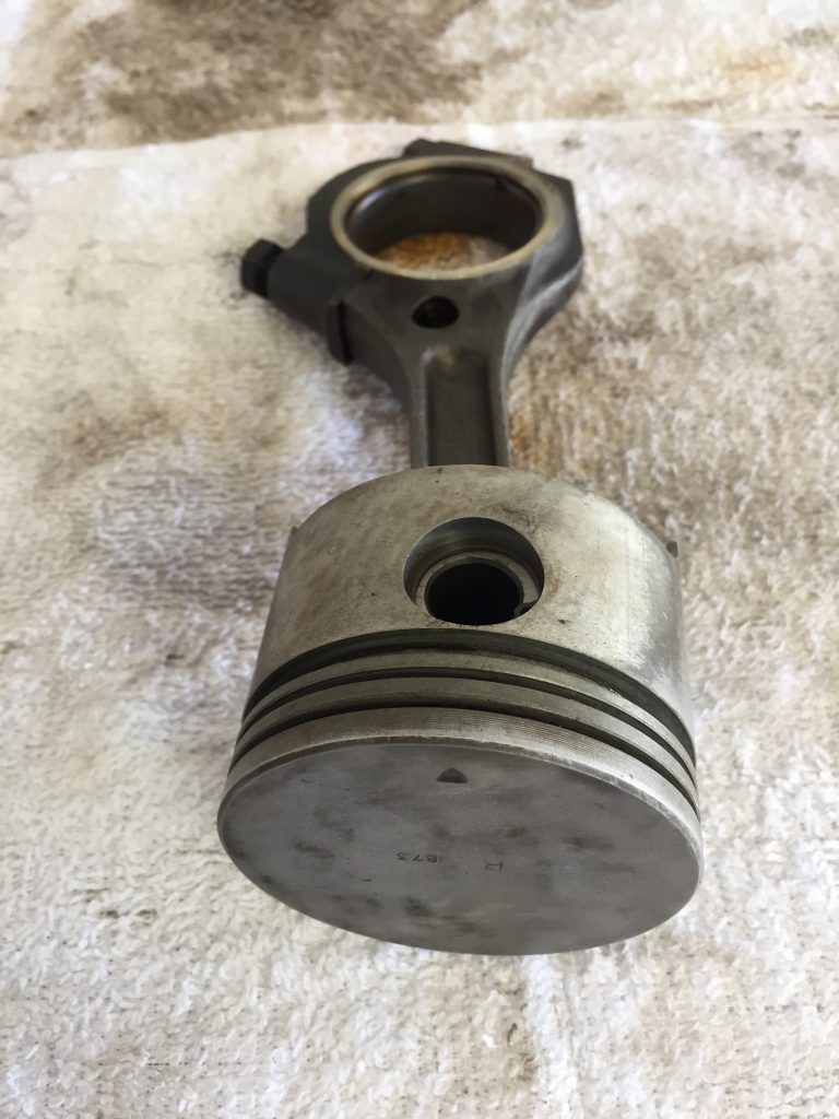
So much fun with just a rod and a fileRemoving metal to get rid of sharp edges and ridgesGot rid of some weight, too. They’ll be peened later, at HDSSmooth, and now they each weigh 640 gramsMinimal work getting rid of sharp edges here, tooNothing drastic was done in the portsJust a little cleanup, imagining the airflowModified intake manifoldThe originalReady to measure combustion chamber volume
Easily one of the most enjoyable parts of my rebuild was the file work on the connecting rods. I have read the stock connecting rods weigh in at 684 grams, which means I filed about 44 grams off each. My aim wasn’t lightening them, though, just wanted to remove any sharp edges, grooves, etc., that might be a point of failure by propogating cracks. HDS would restore surface strength with their peening process.
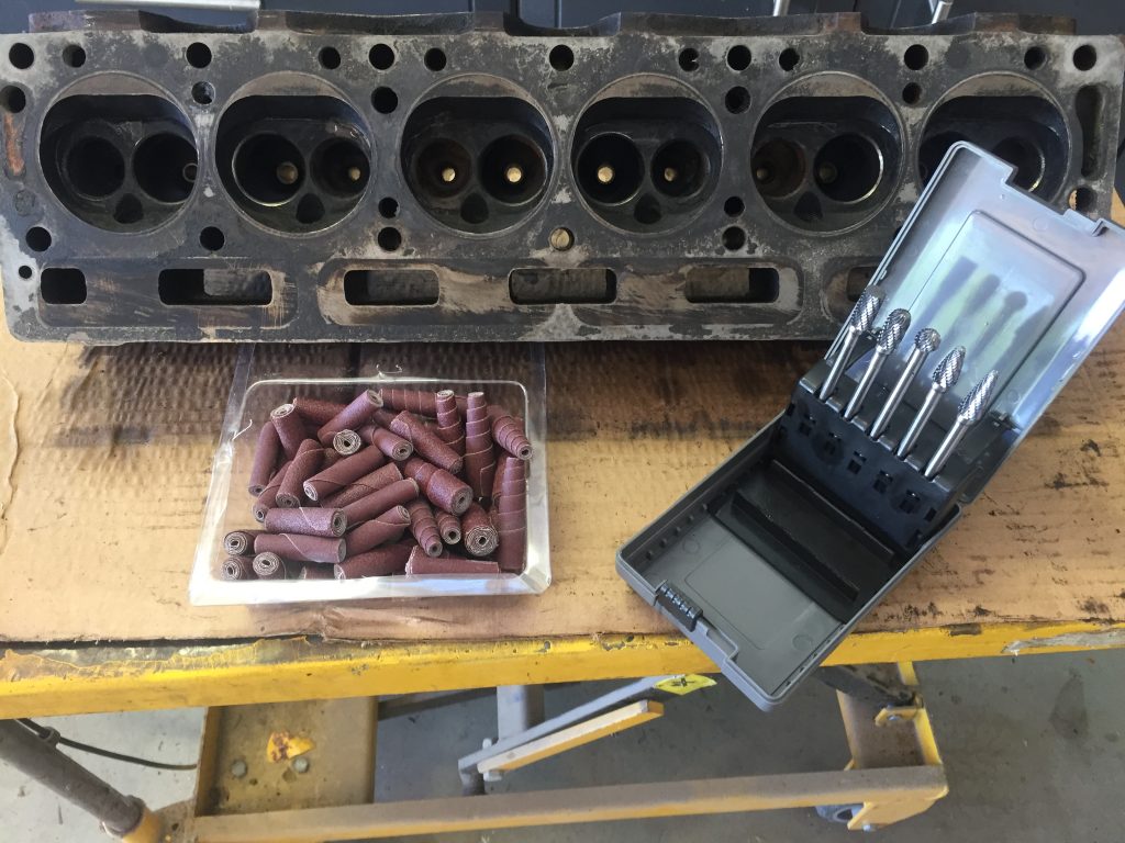
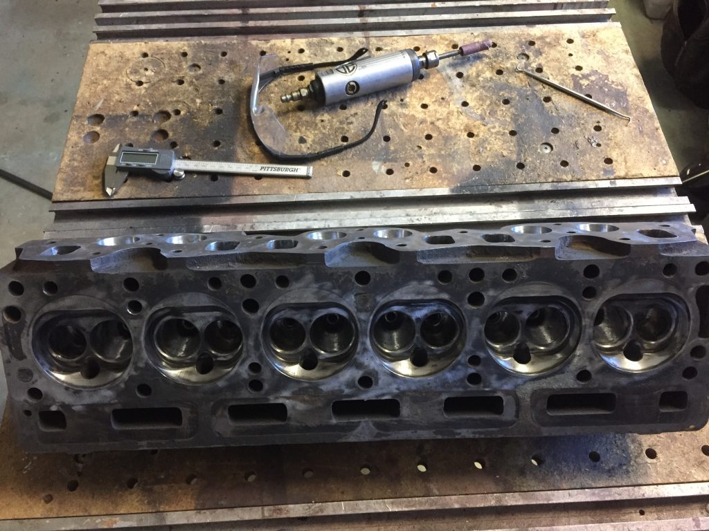
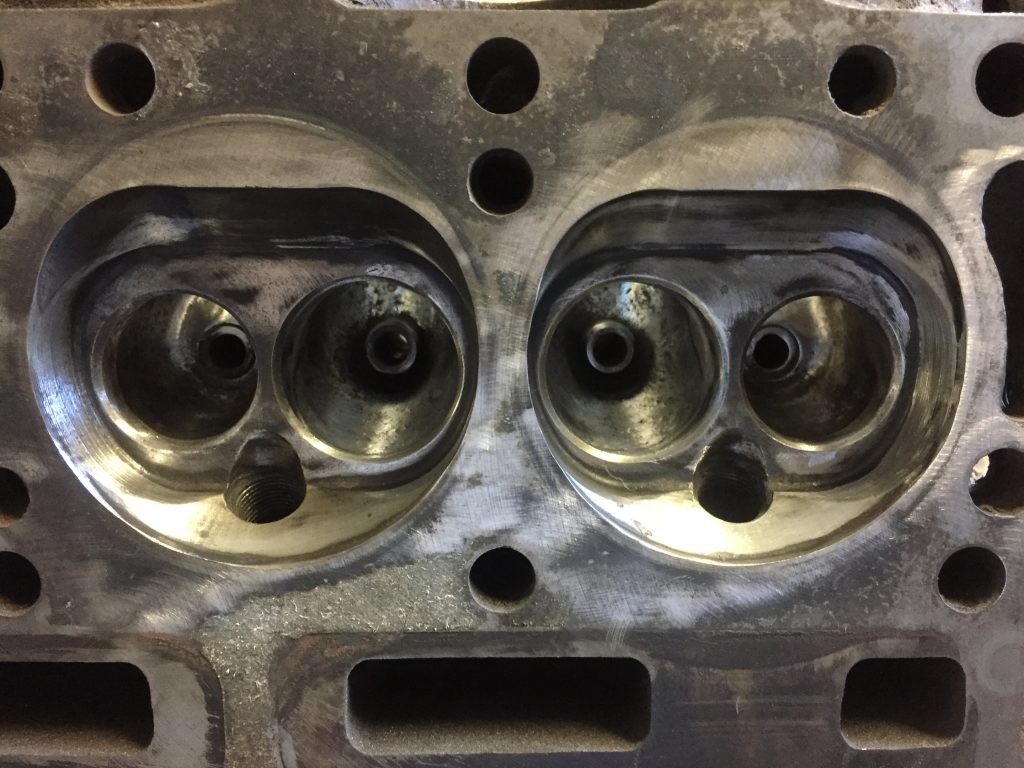
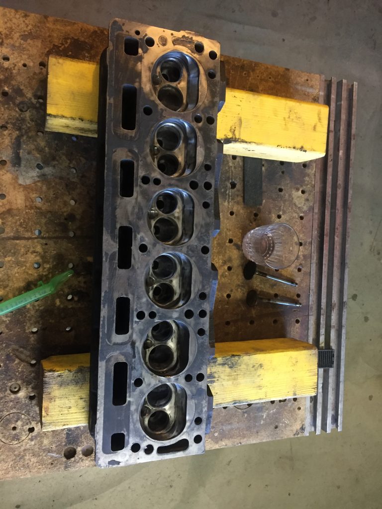
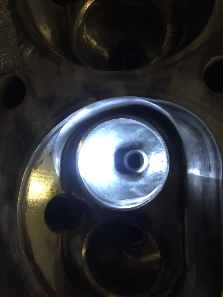
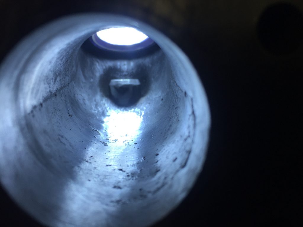
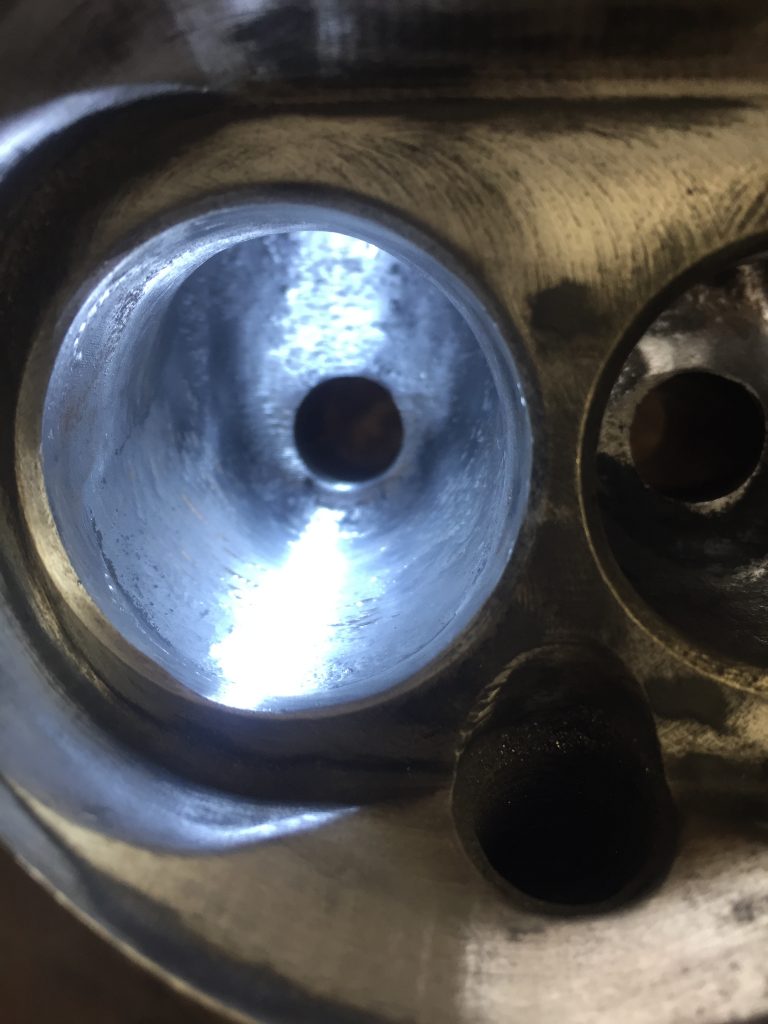
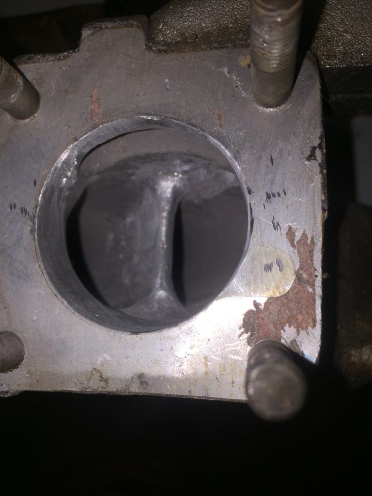
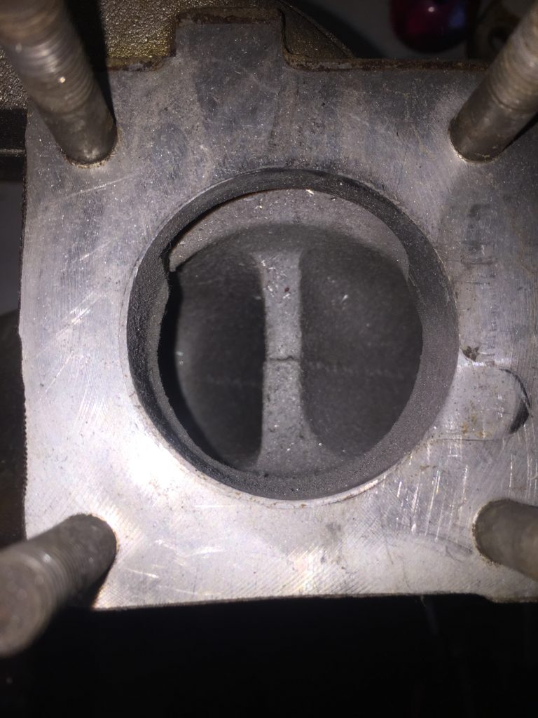
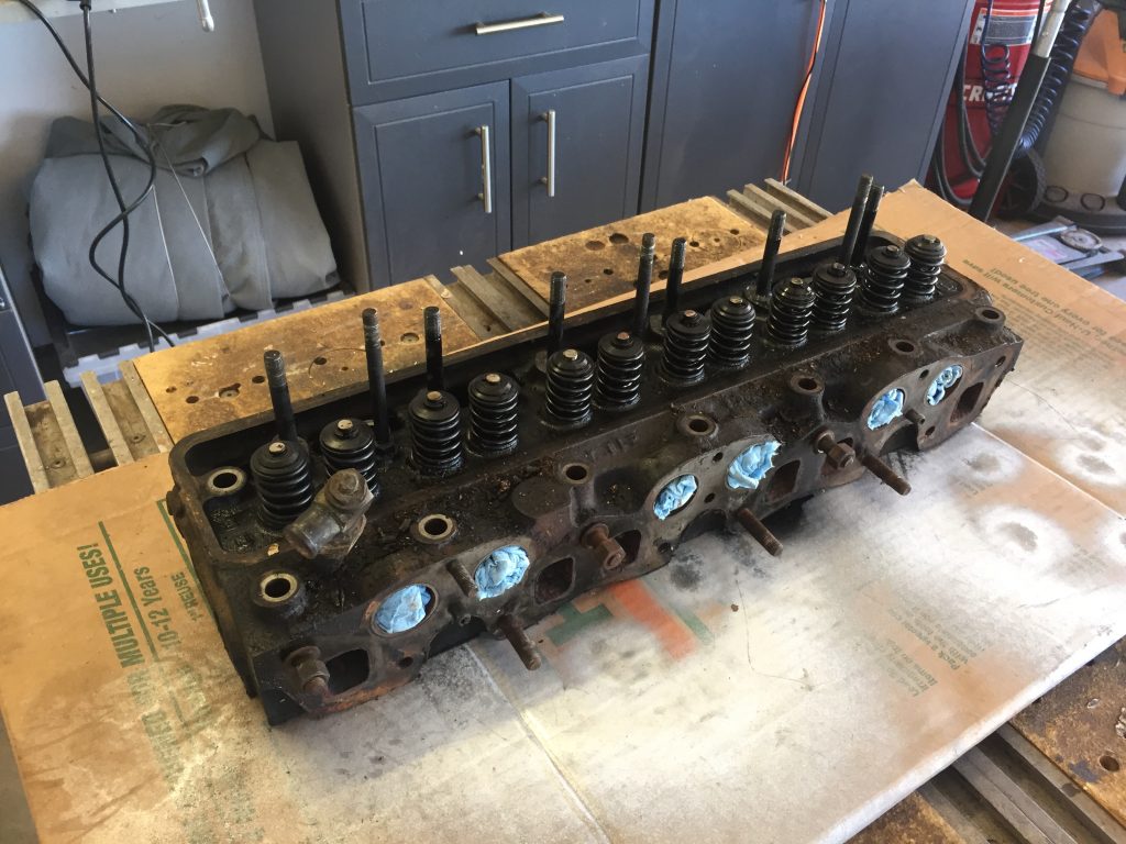
With the ports and manifolds, my goal was just to clean them up a little to aid the flow. I would advise being very careful around the valve seats… make sure you leave enough material to insert new seats and still have a nice smooth transition to the port with no big pockets behind the seats. I tried to be very conservative there.
In the combustion chambers, I was again just focused on removing sharp edges to eliminate hot spots and smooth things out a little bit. It comes at a very slight cost in terms of compression ratio since I was making the chamber a little larger in volume. I was asking HDS to lop .140 of the heads, so it was of no concern at all.
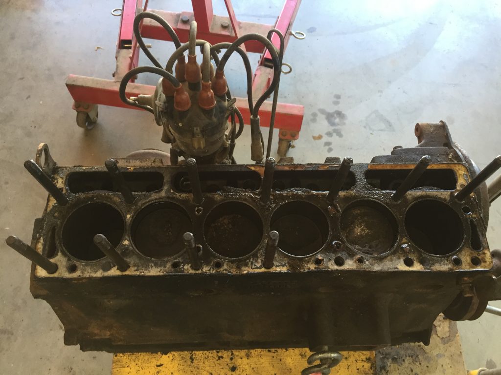
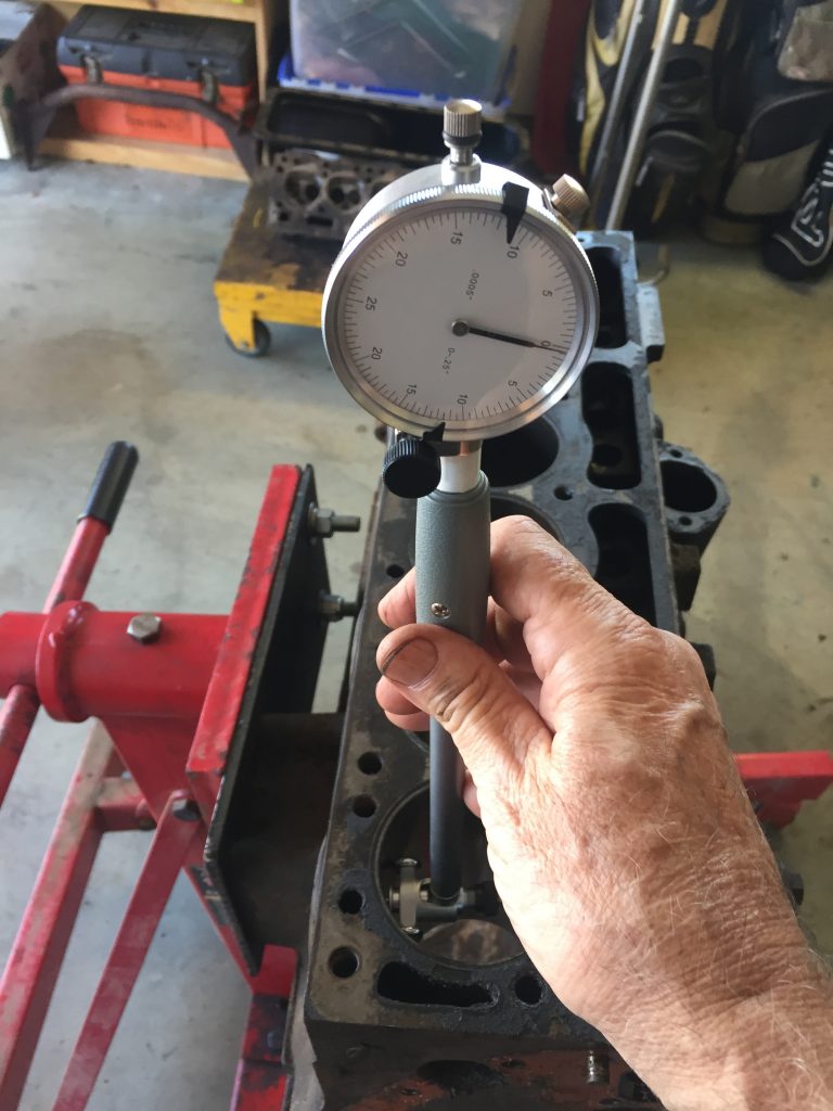
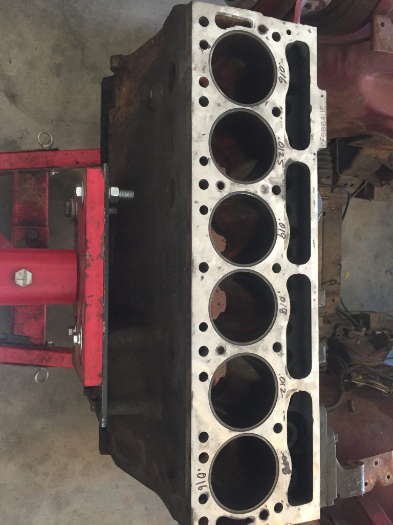
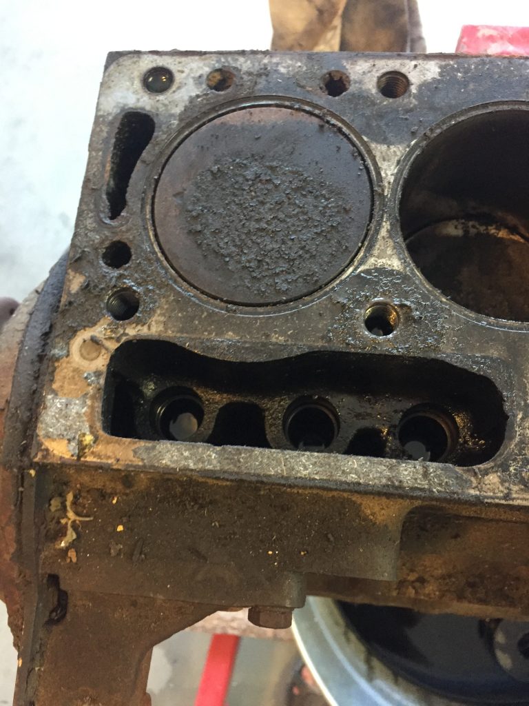
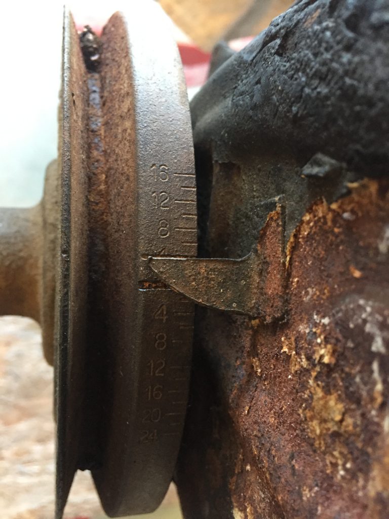
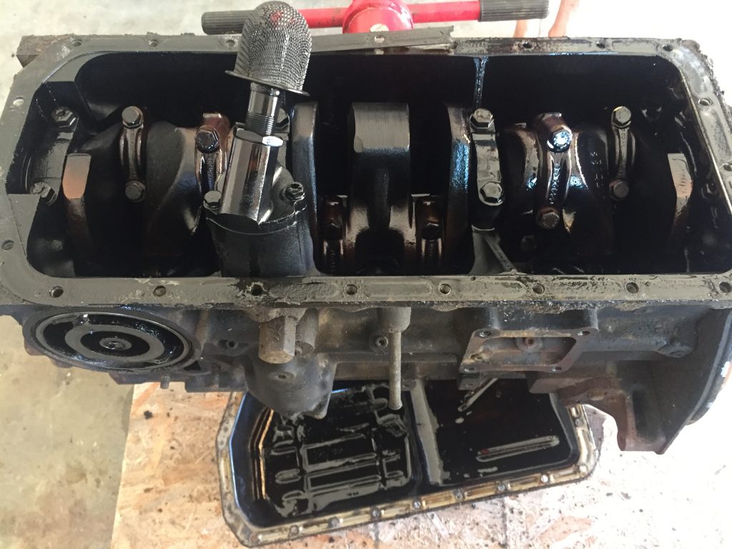
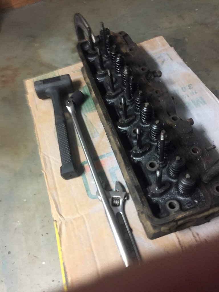
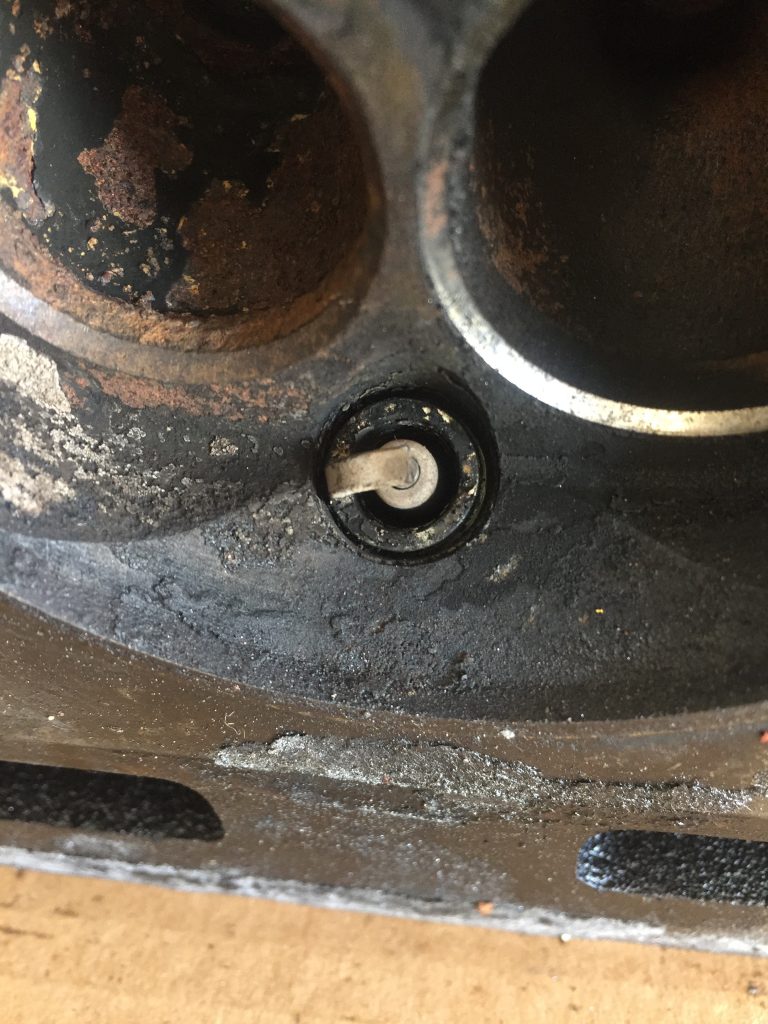
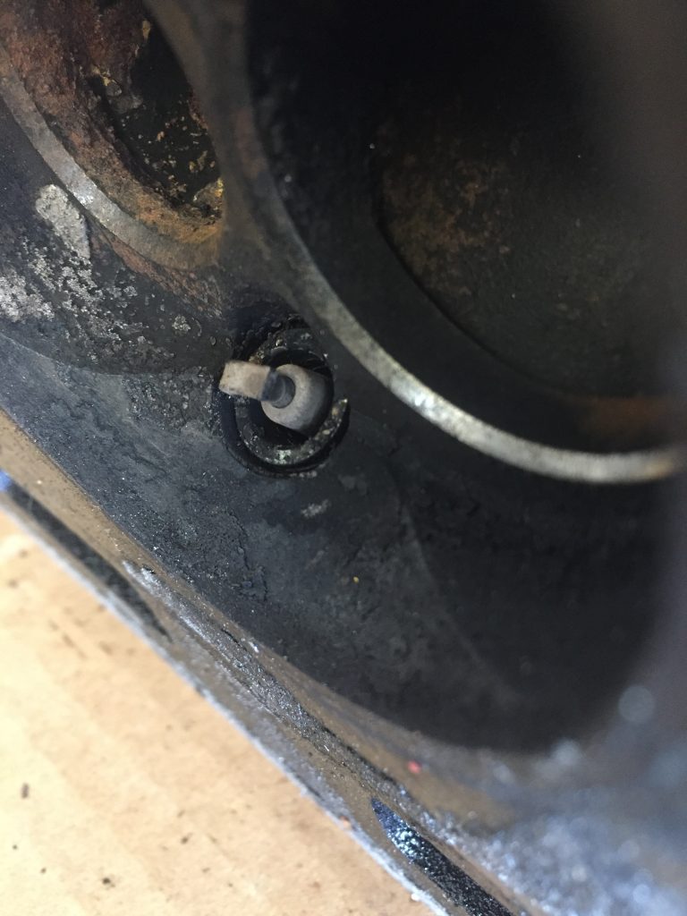
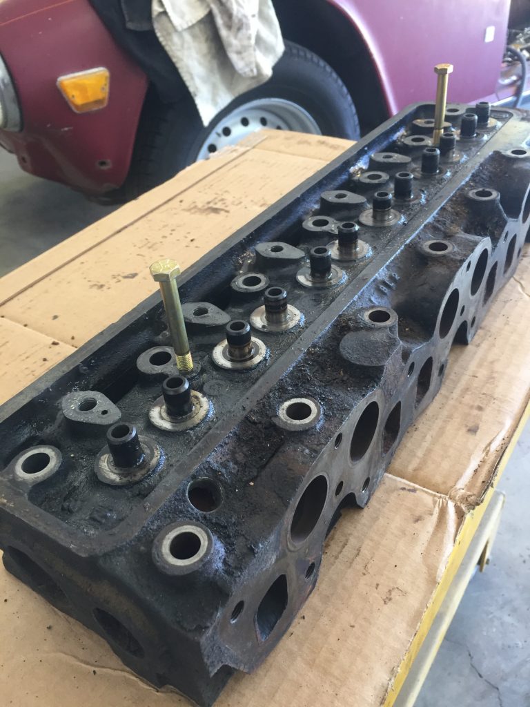
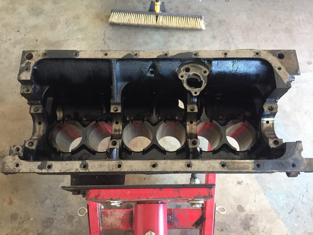
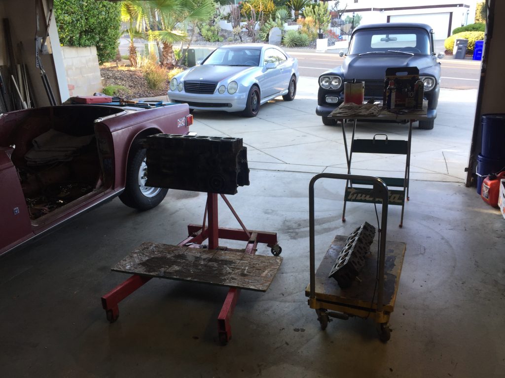
Measuring the boresNoting the position of the oil pump drive slotsPiston/rod assemblies coming outCarbon buildupLots of combustion chamber cleanup to doHead is stripped except for guidesRotating assembly gone, block almost ready for machine shopHmm… how much can I increase the compression?Cleaned up piston, but HDS wanted to bore the cylinders, so these were not used
Well, everything looked as expected for an engine that probably hasn’t been freshened up since it was manufactured nearly fifty years ago. The cylinders looked fine to me, as did the pistons, but my machine shop of choice HDS/Carquest in San Marcos thought otherwise. Casey, the owner, knows what he’s doing. I absolutely trust him. Before getting the block and head over to him for the serious business, I decided to clean up the combustion chambers, ports, and connecting rods myself, as shown in subsequent posts.
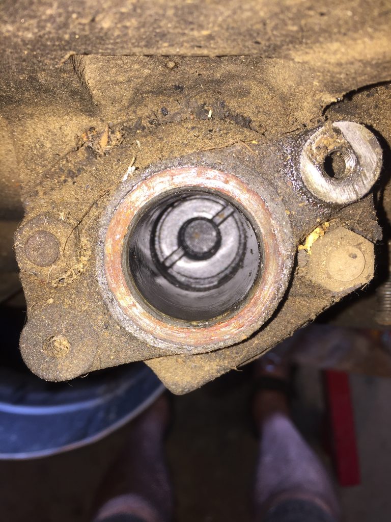
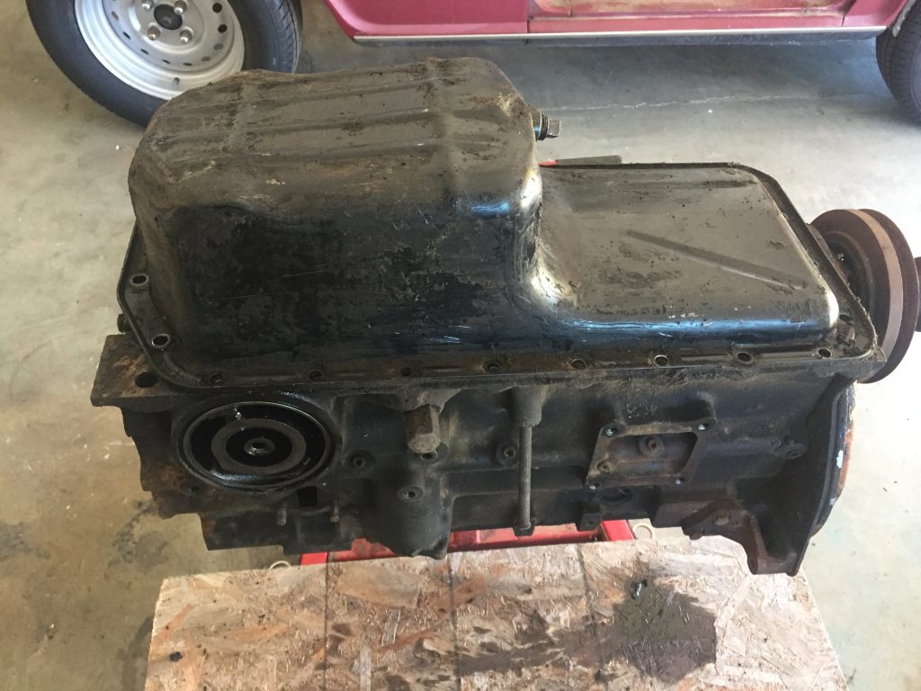
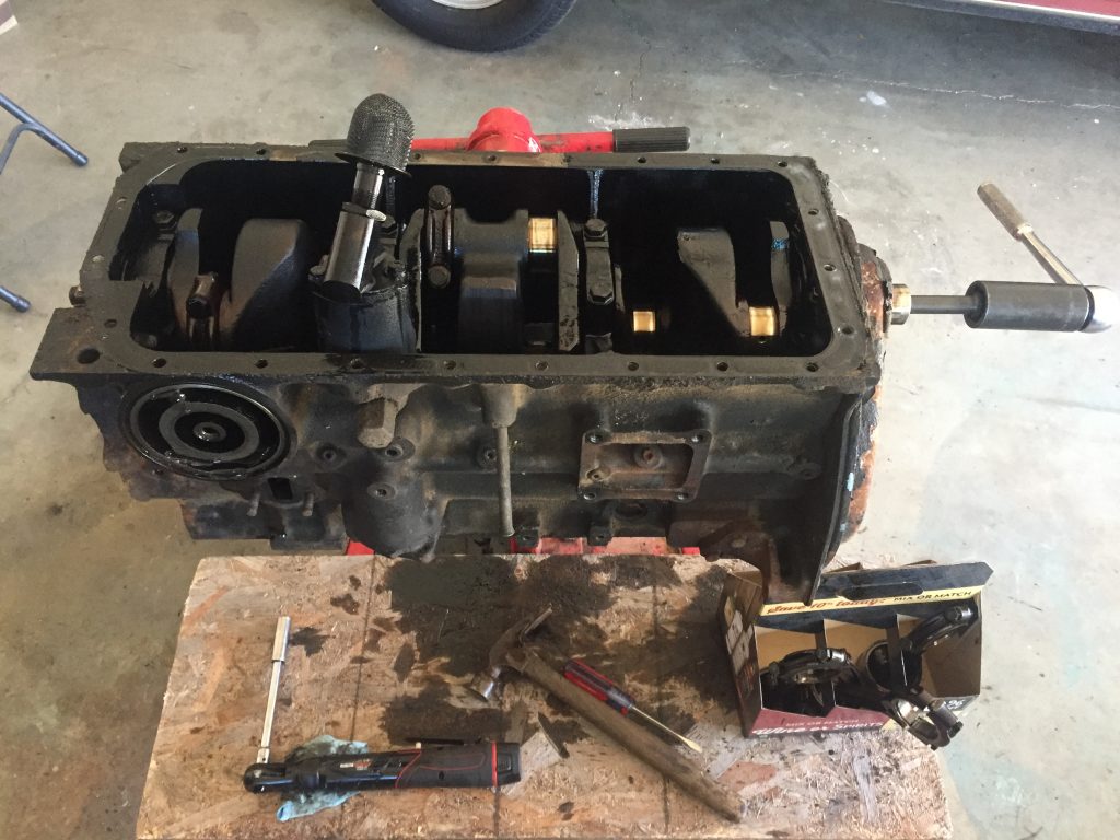
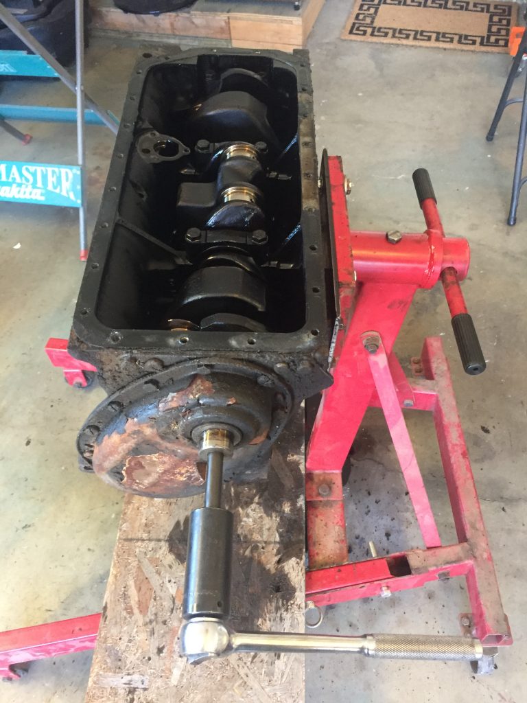
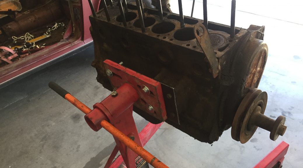
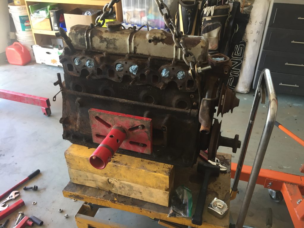
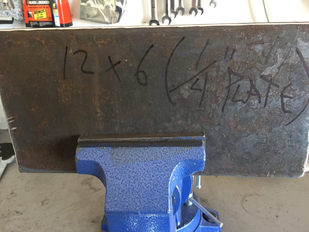
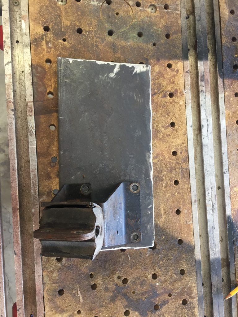
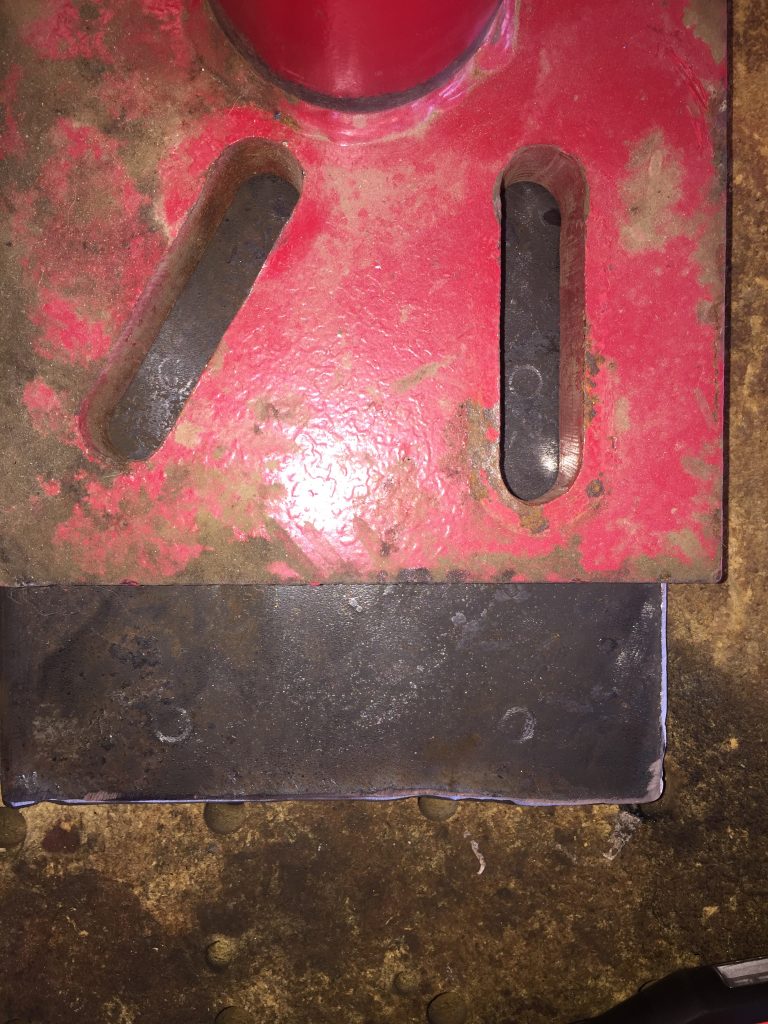
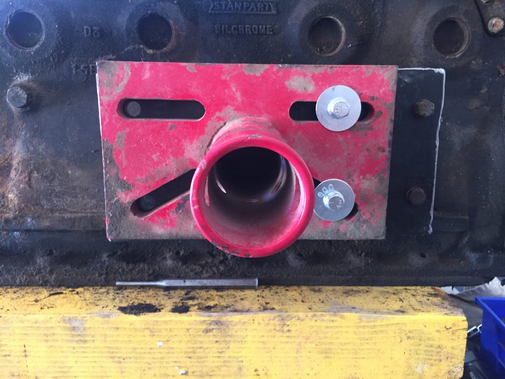
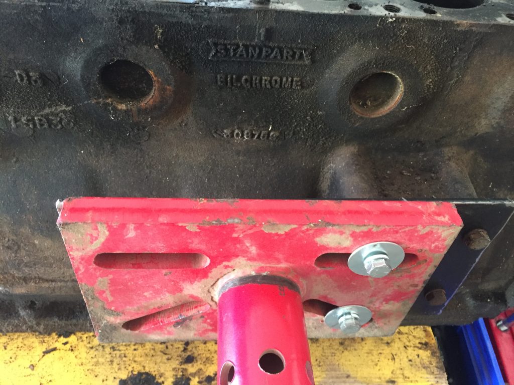
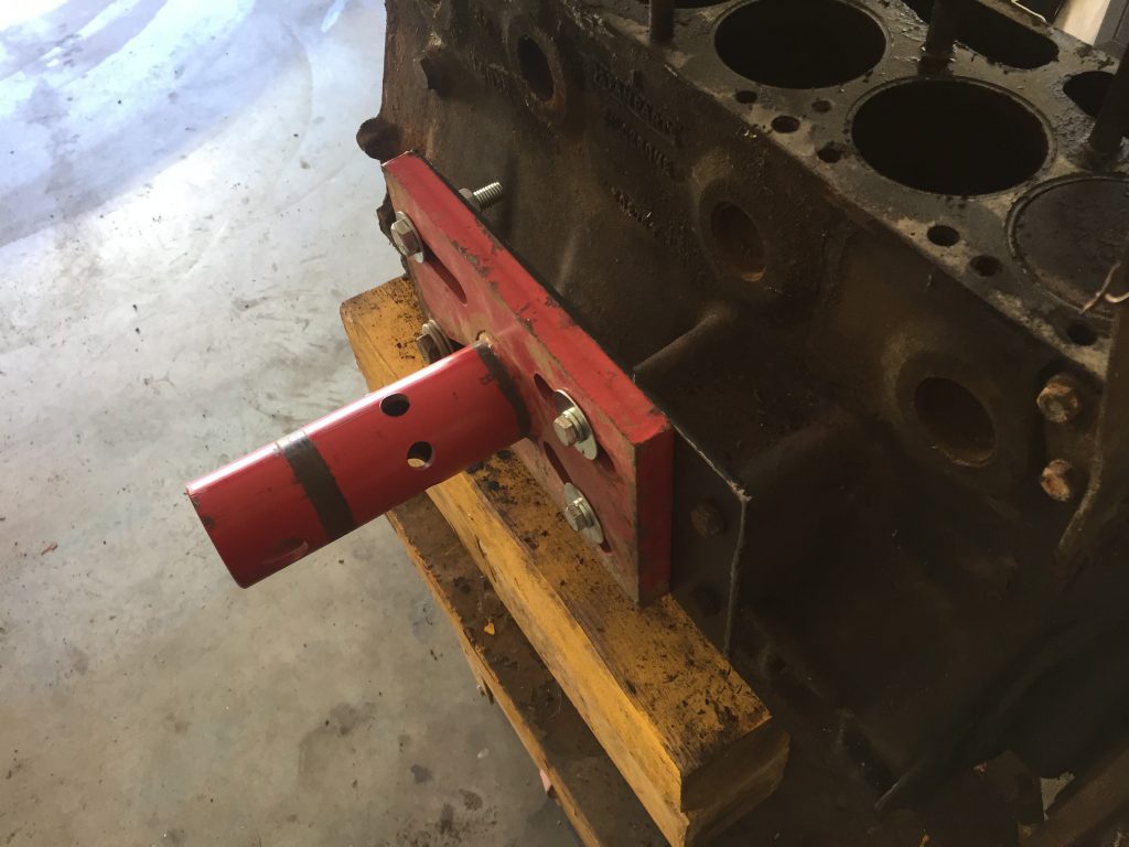
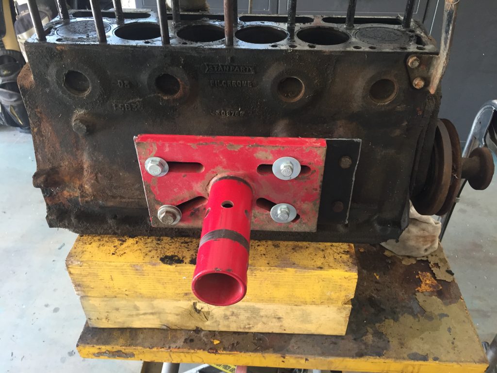
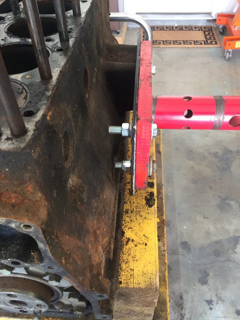
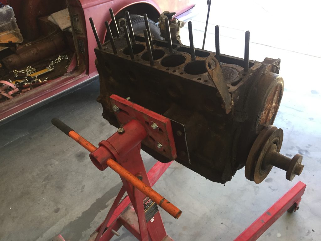
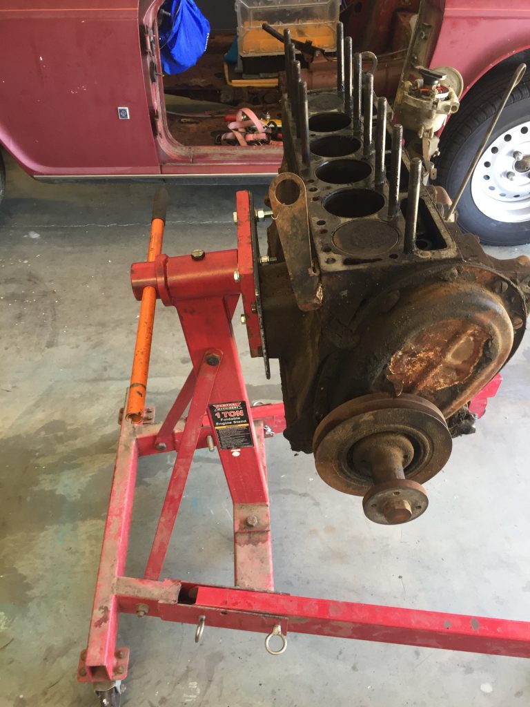
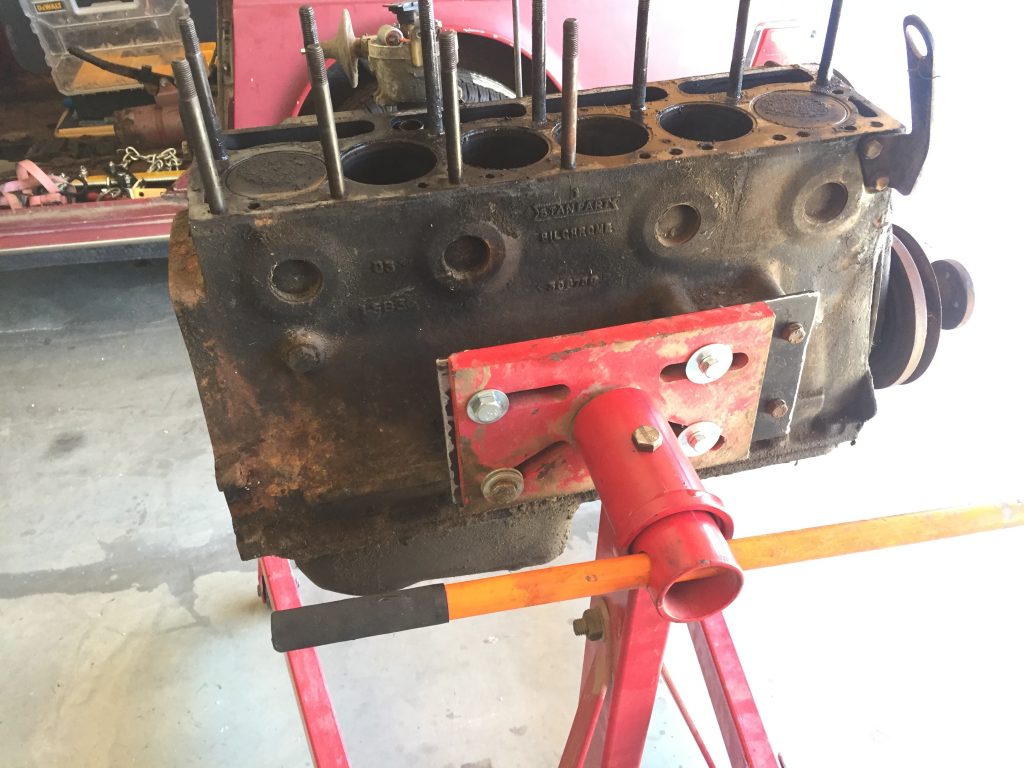
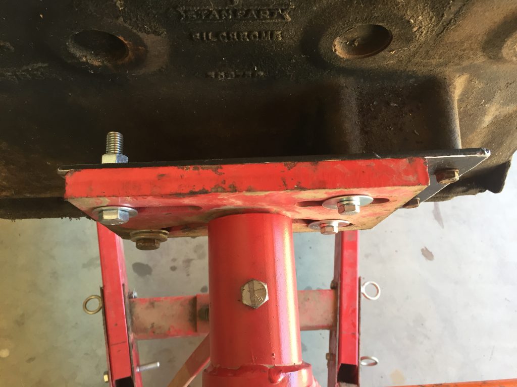
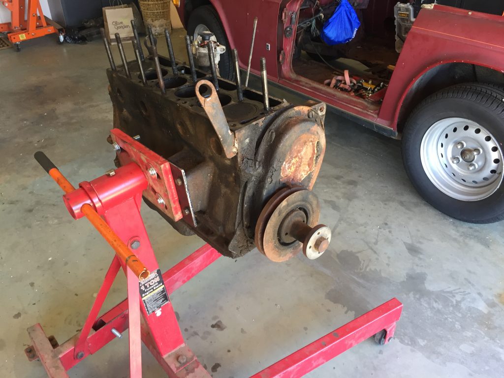
Will this work?1/4 plate was beefy enoughEngine mount used as a template for holesYep it works, easy to rotate the engineSide mount worked out well for the TR6Piston tops and cylinders looked decent
The other engines I’ve rebuilt were always mounted onto the stand at the rear of the block. After reading what other TR6 owners had done, I chose the side mount. This worked out very well, and the 12″x6″ quarter inch thick plate was plenty strong… no flexing or movement at all.
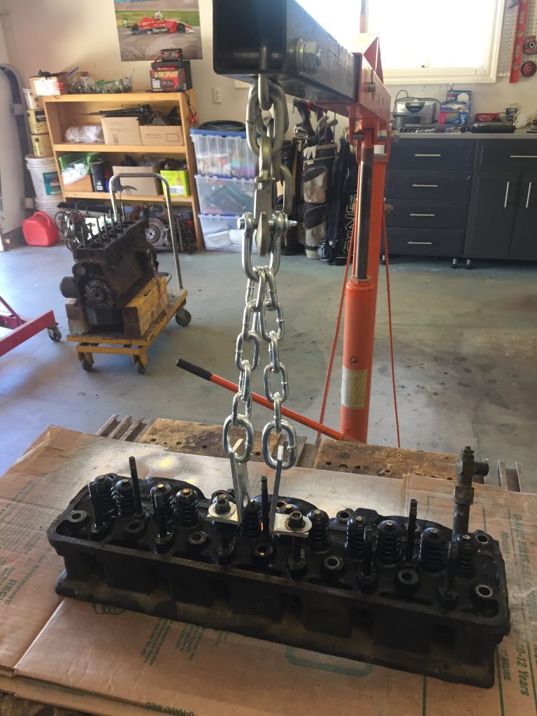
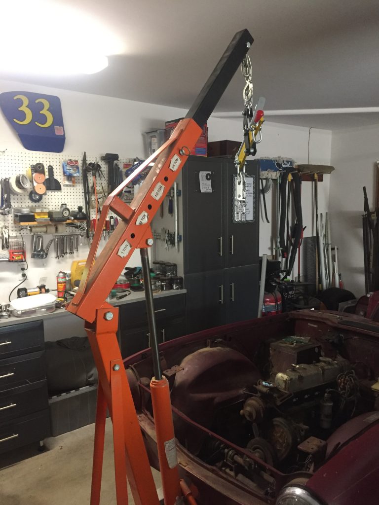
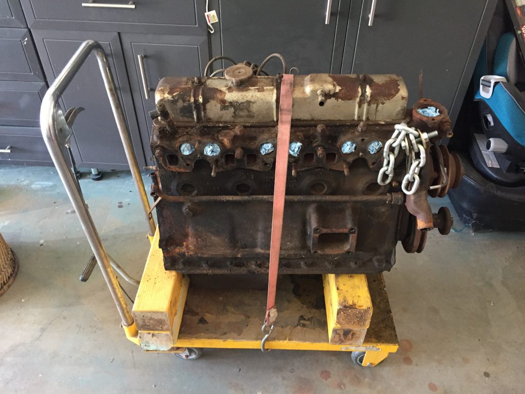
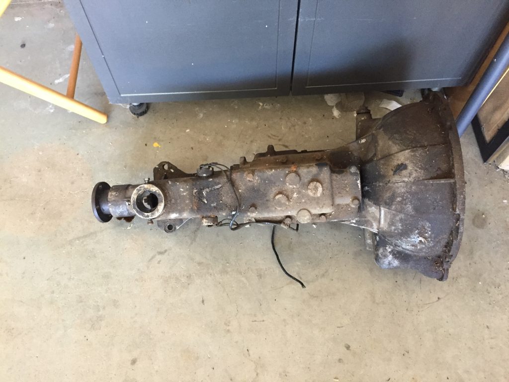
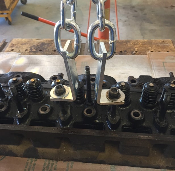
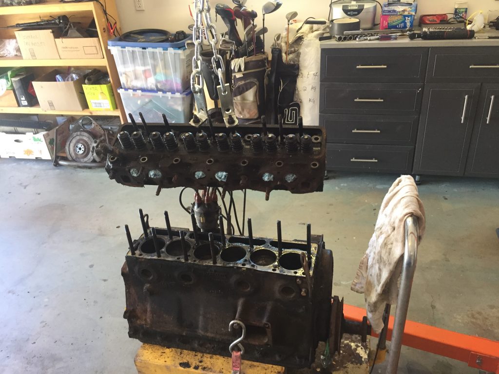
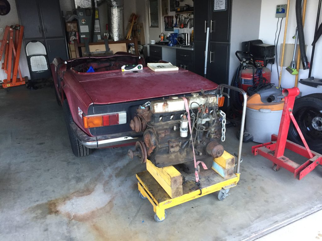
Added strength because hoist is fully extendedMaking sure I could lift it high enoughEngine was removed with transmission then separatedThere’s a hole in my TriumphHead removalLighten the load for the engine standEngine removal crew: wife Linda and our friend Ellen LawsonOld friend and racer Chuck Burnett “supervising” engine removal
The engine removal was straightforward. I left transmission and cylinder head attached, but removed manifolds and alternator, disconnected driveshaft, wires, and hoses. The head was stuck on the block so we used the hoist to separate it from the block, making sure it was pulled up evenly. Because the hoist was fully extended to the 1/4 ton hole, I added a reinforcing square tube all the way to the hook, which required drilling a hole for the 1/4 ton pin.
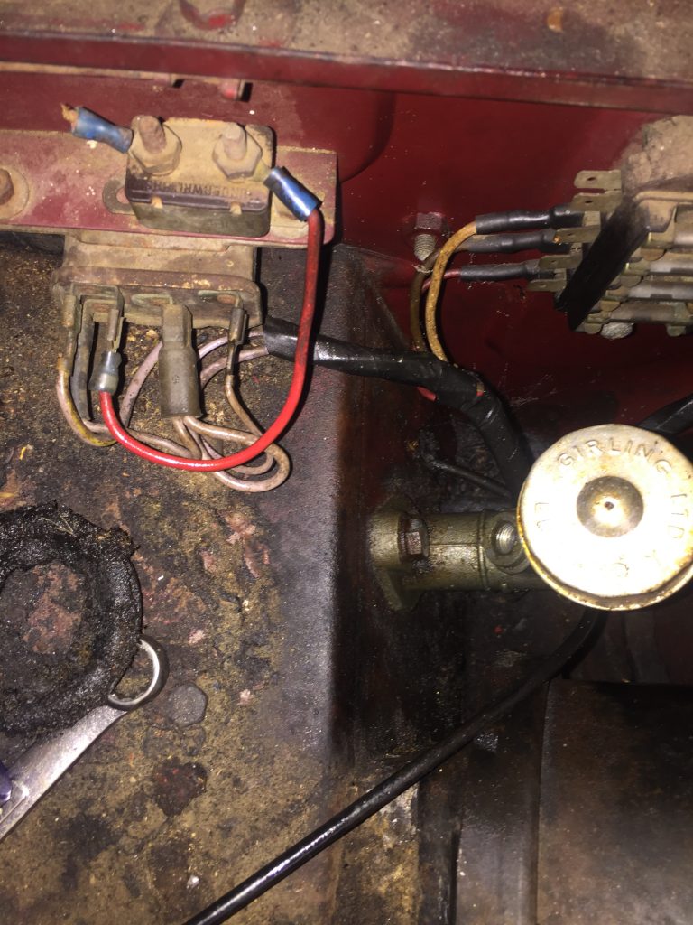
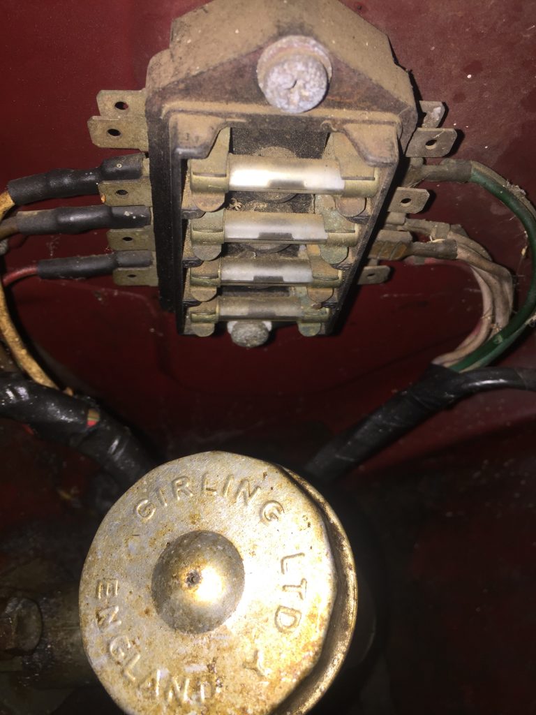
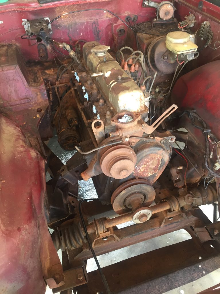
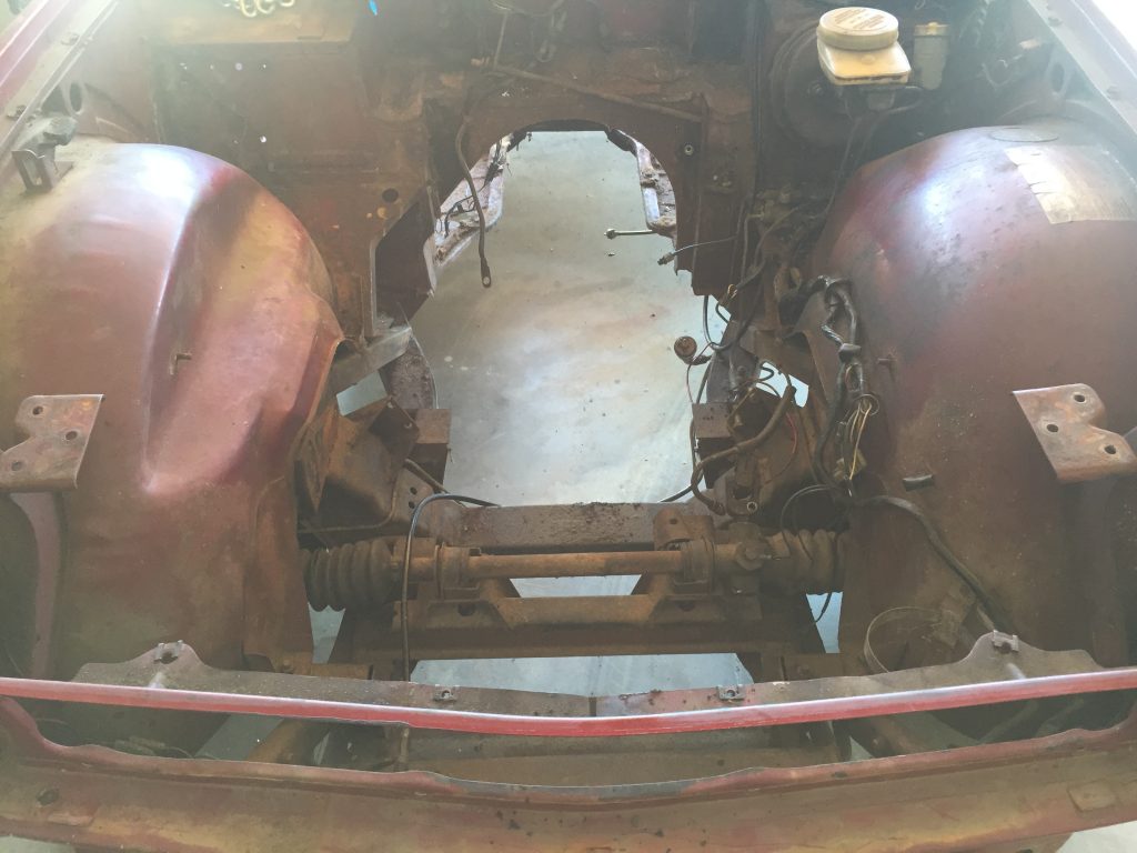
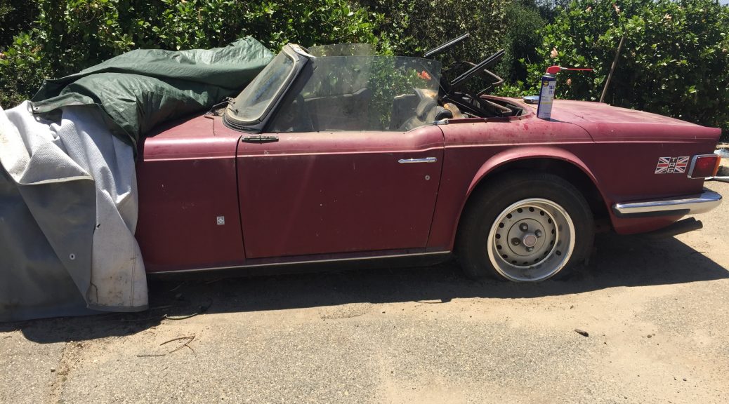
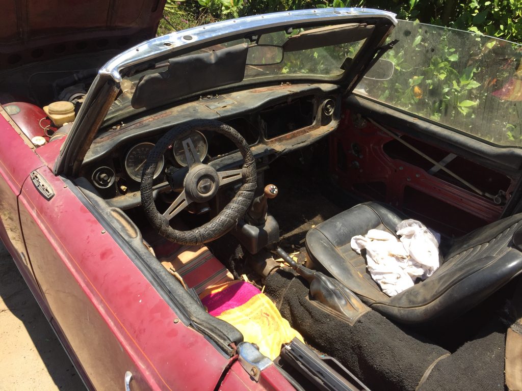
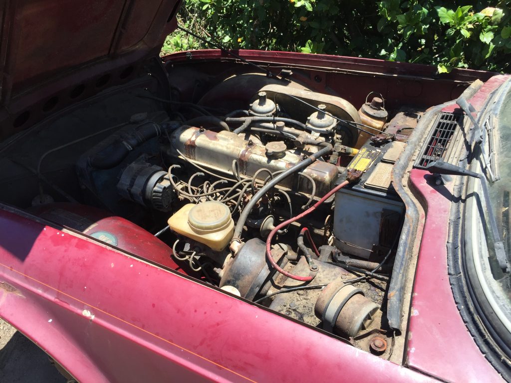
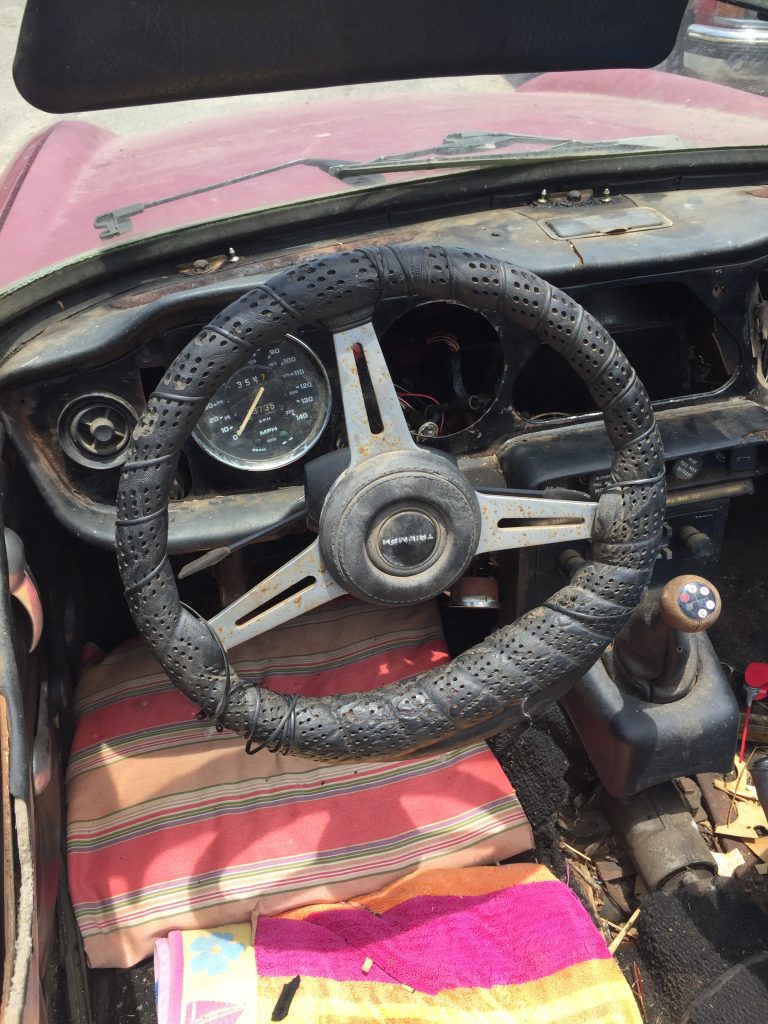
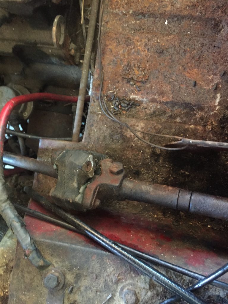
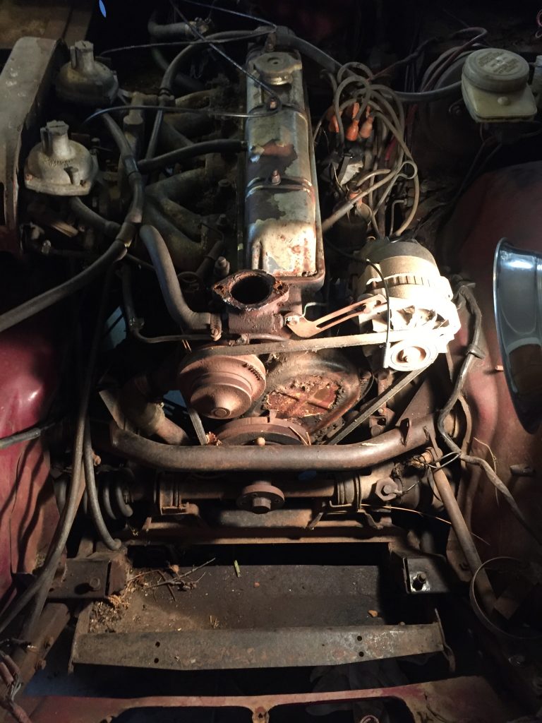
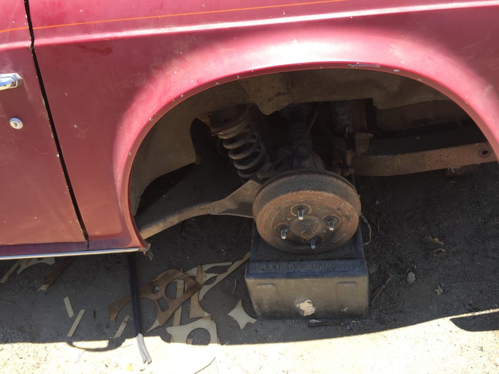
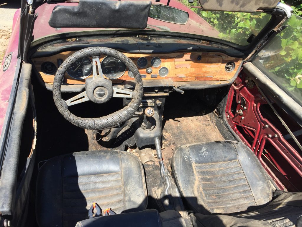
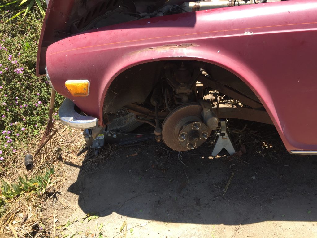
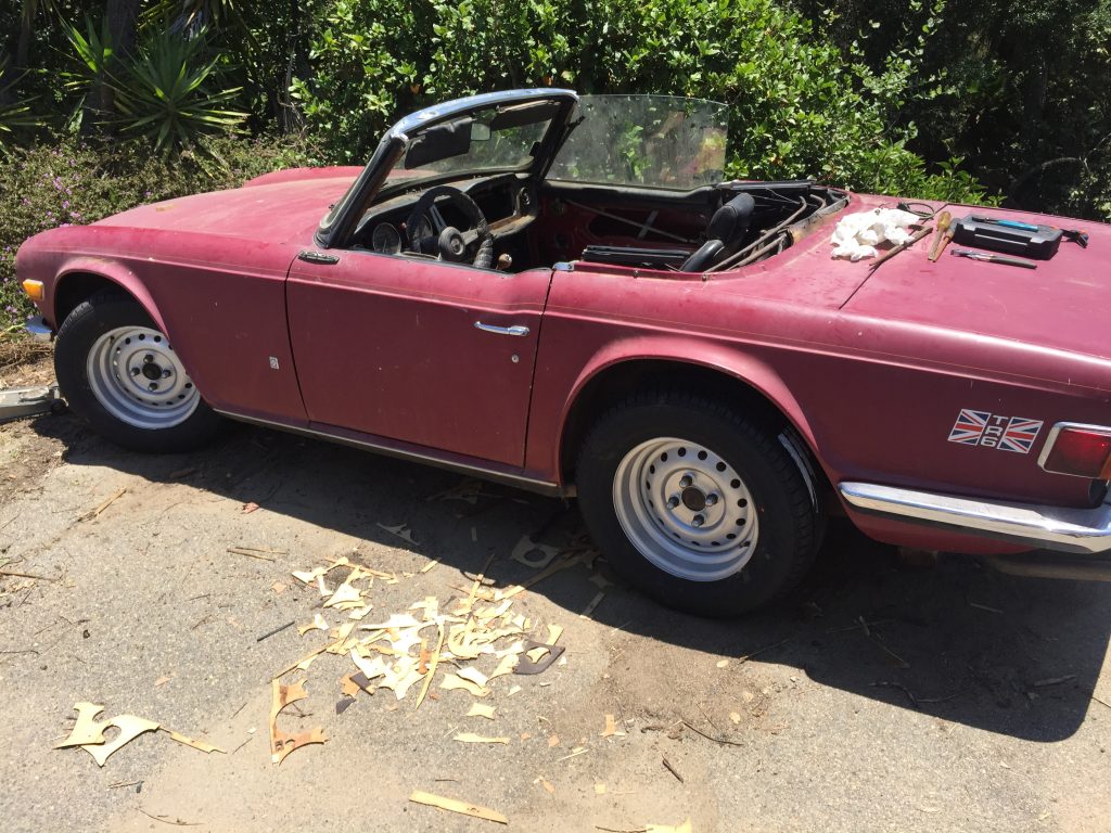
Here are a few pictures depicting the state of the Triumph after sitting outside under a fabric car cover for twenty years… thank goodness it resided in Southern California. But it was truly a rodent hotel.
Just to get it home I needed to buy two new wheels and four tires. And find a locksmith… the keys were missing and the steering was locked.
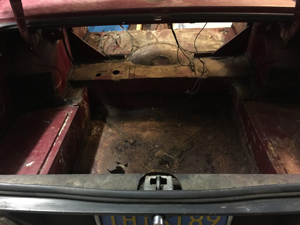
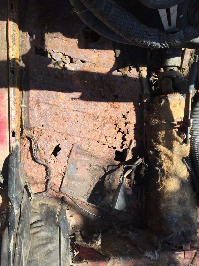
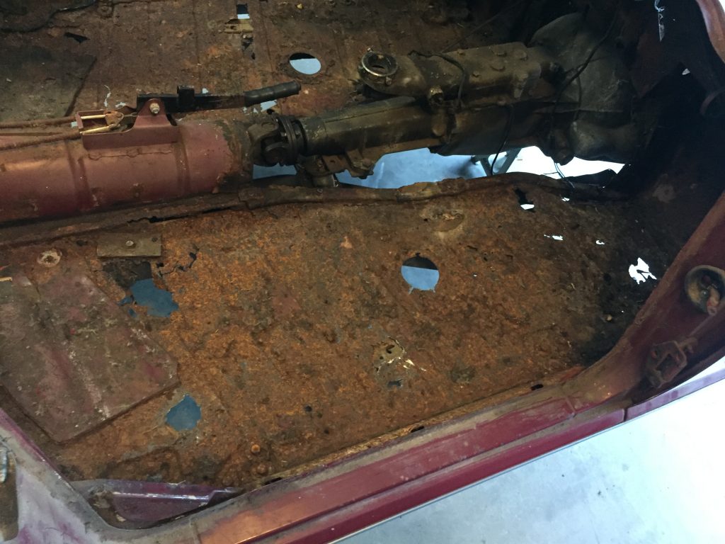
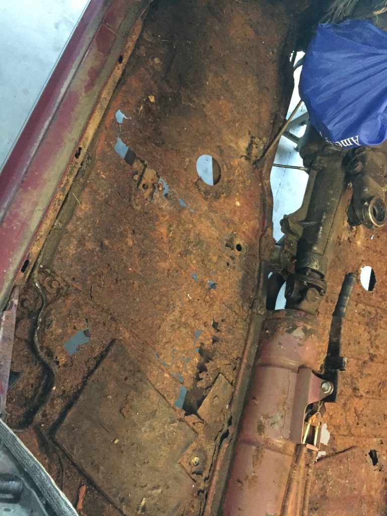
Clearly we are looking at new floor pans in the passenger area, as well as the trunk. And pretty much everything else!
One word of advice for you when cleaning out an old car that has been host to rodents… MASK! The trunk, for example was at least four or five inches deep in droppings and twigs and nut shells and dirt. Gross.
I was somewhat careful about wearing a mask as we filled a garbage can with rodent droppings and shells and whatever the heck all that other stuff was, but not as careful as I should have been. My lungs have literally never been the same since that original cleanup. This is serious advice, heed it, please! Best practice would have been a good painter’s mask with dual filters, reasonably priced at Harbor Freight. I did utilize one, but there were occasions when I just wore a paper or cloth mask… that is not sufficient.