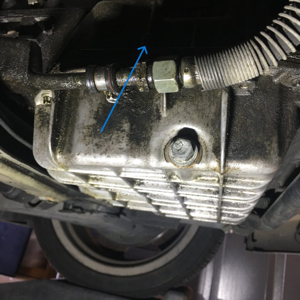
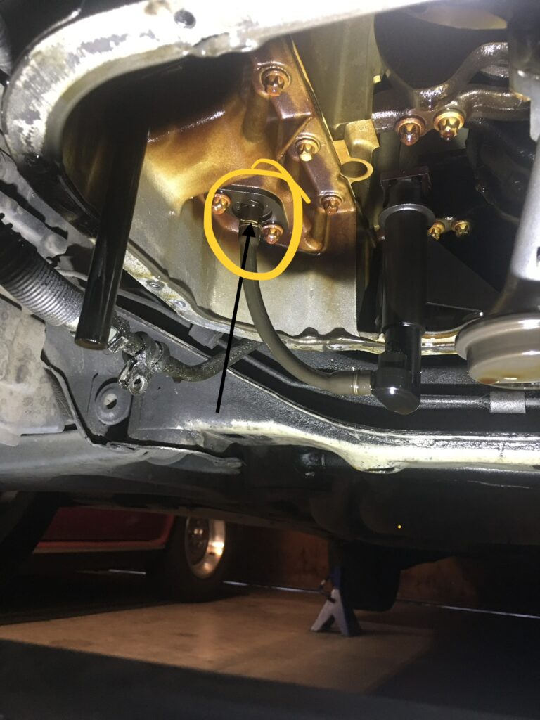
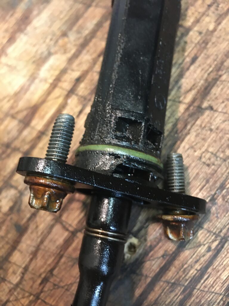
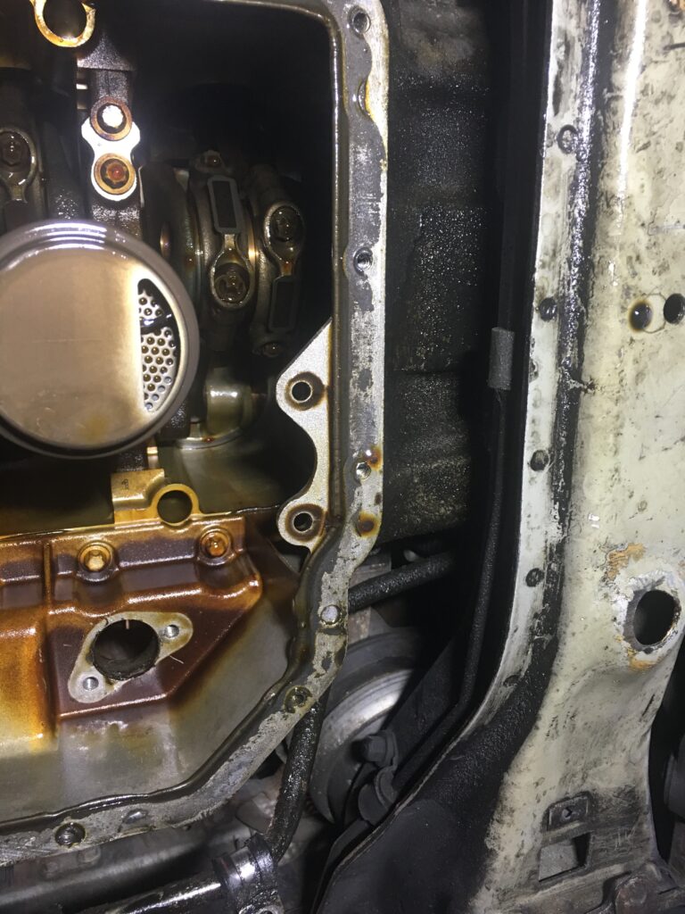
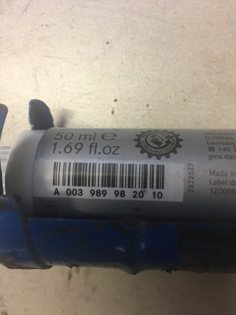
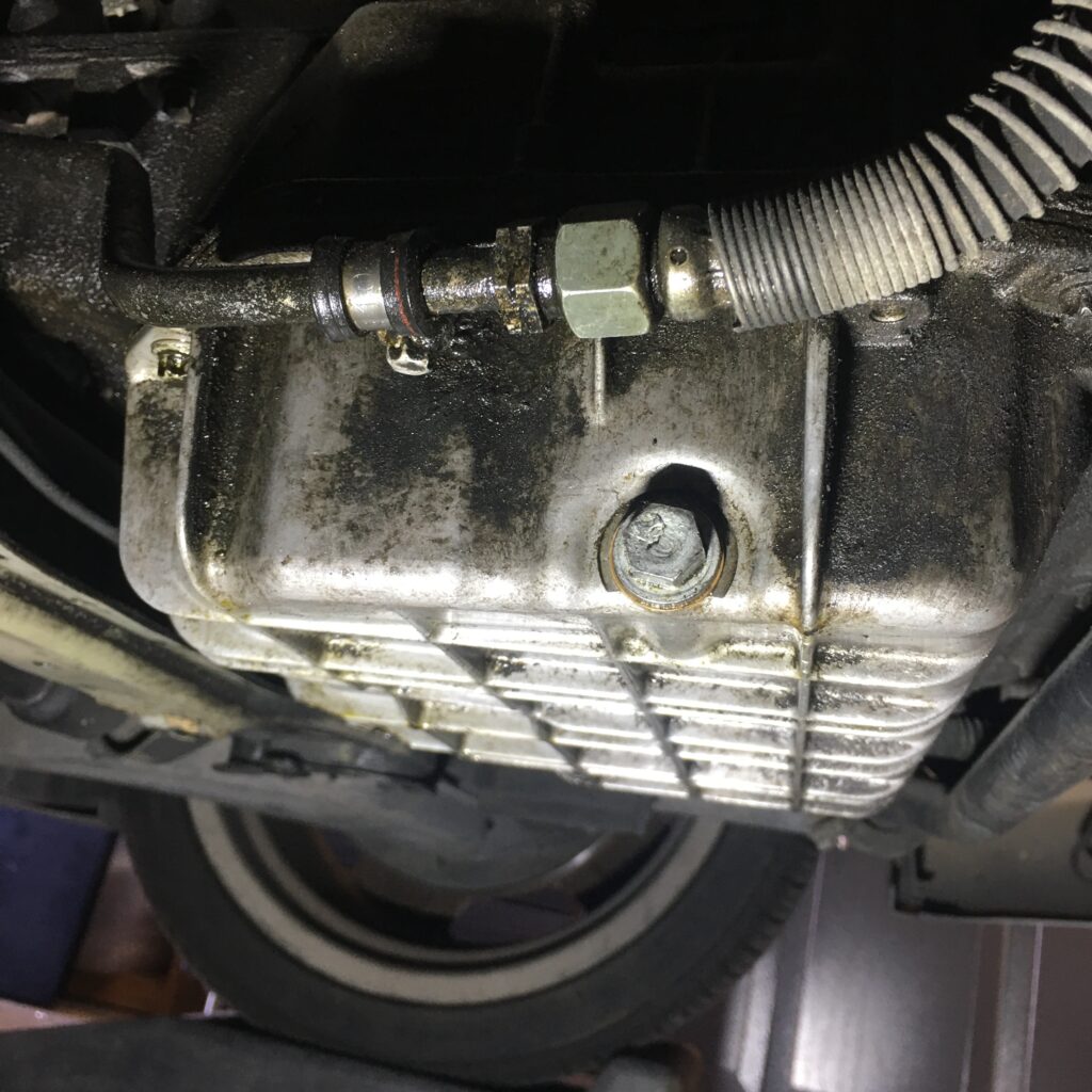
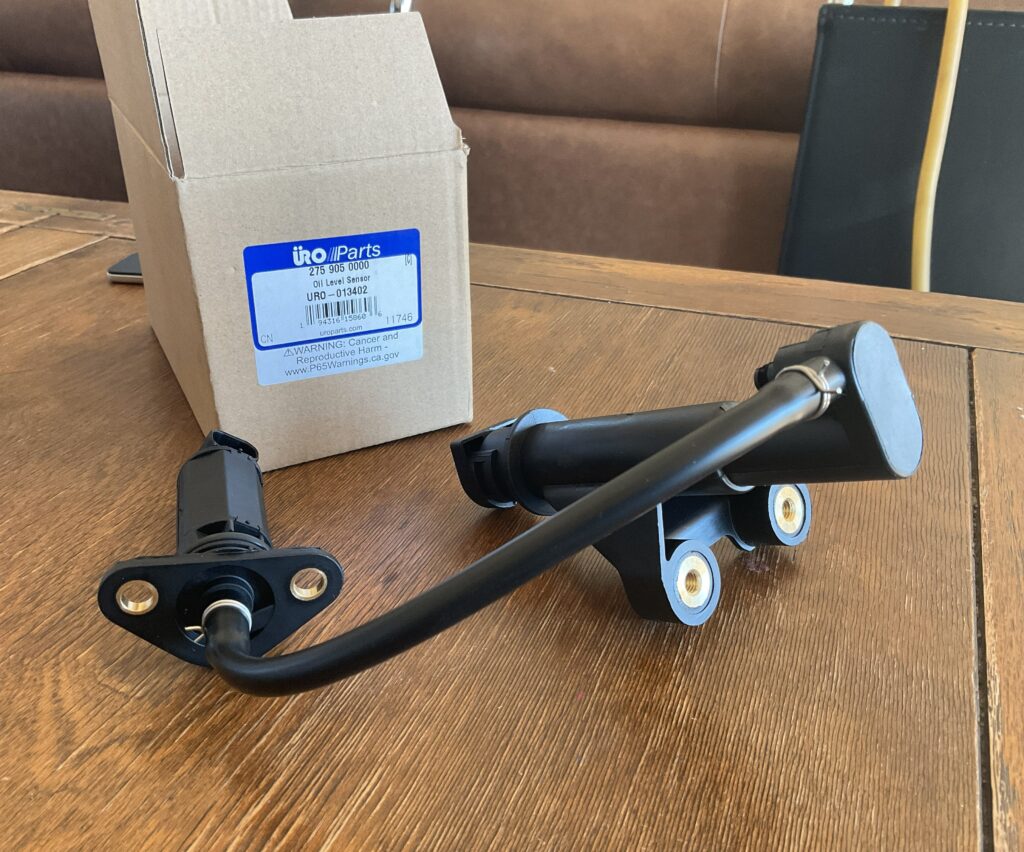
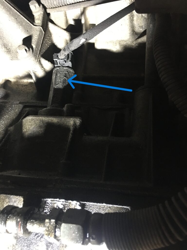
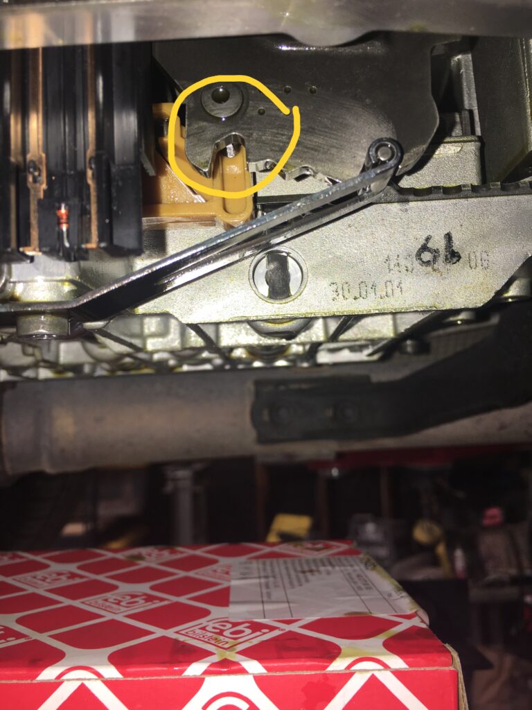
The oil sensor quit working a few months ago. I would have let it go since I check my oil regularly, but in my pursuit of leaks it became clear that the sensor was a problem. These engines have an upper and lower oil pan, both cast aluminum. The oil sensor is bolted to the upper oil pan and is accessed by removing the lower pan. Part of the oil sensor protrudes through the upper oil pan in a little flat area, approximately above the drain plug, where a connector plugs it into the ECU. The rubber o-ring was no longer doing its job of keeping the oil inside the engine.
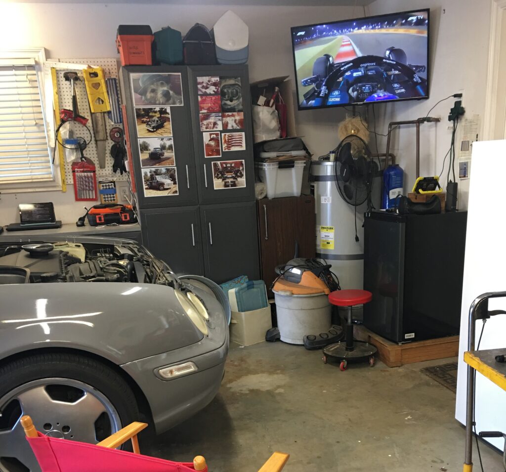
It was a mistake to have F1 on the TV, apparently I can no longer multi-taskThe sensor shows itself here, above the drain plugWhere the plug connects sensor to ECU
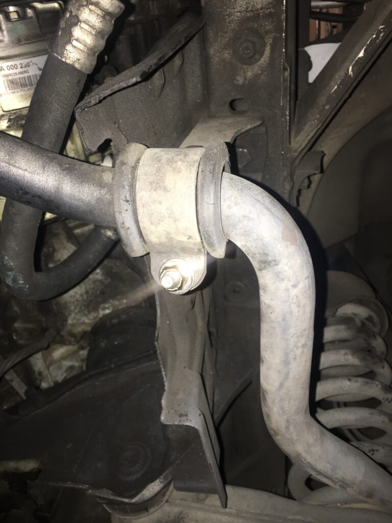
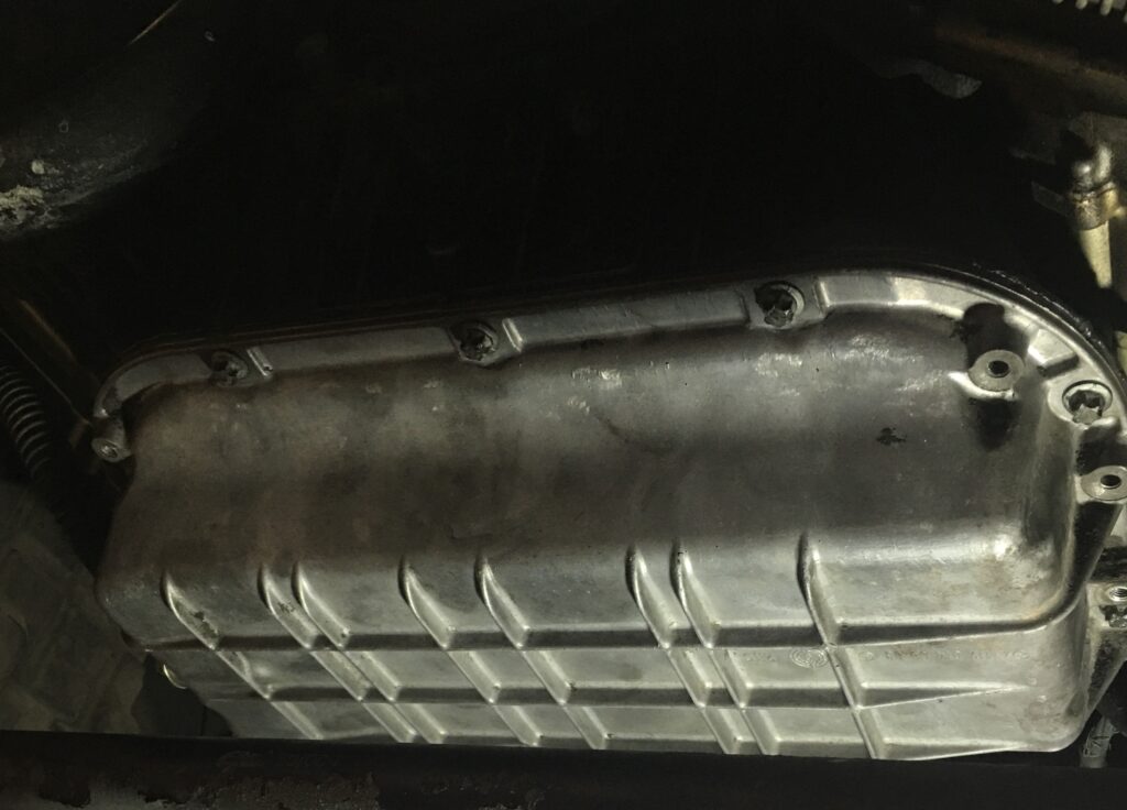
I used the E10 socket to remove a dozen bolts securing the lower oil pan, plus two more holding pipes to the pan. Then I removed the two brackets holding the sway bar in position under the oil pan, allowing it to swing down and out of the way. As long as the front wheels are at the same height there should be no tension on the sway bar, and it doesn’t matter if they’re on a ramp like mine or hanging freely.
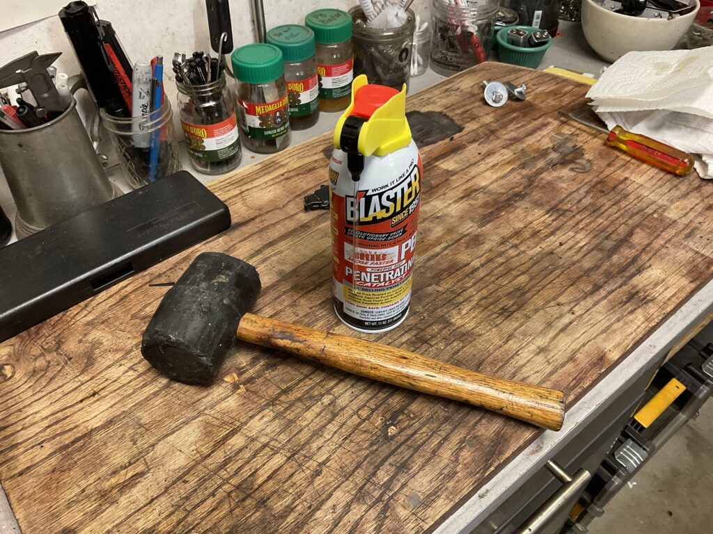
The pan felt like it was welded on, and wouldn’t budge even with several hard raps with the rubber mallet, side to side and front to back. I sprayed PB Blaster liberally all the way around where the two pans join and let it sit overnight. The next morning, a couple more knocks with the mallet broke the seal loose.
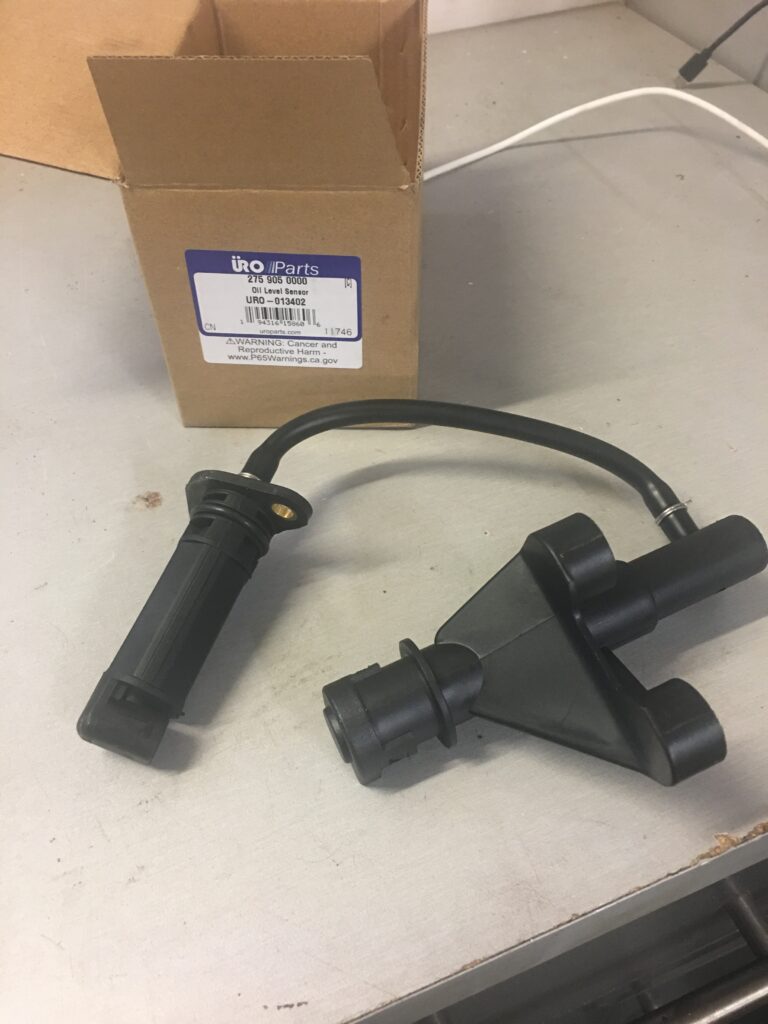
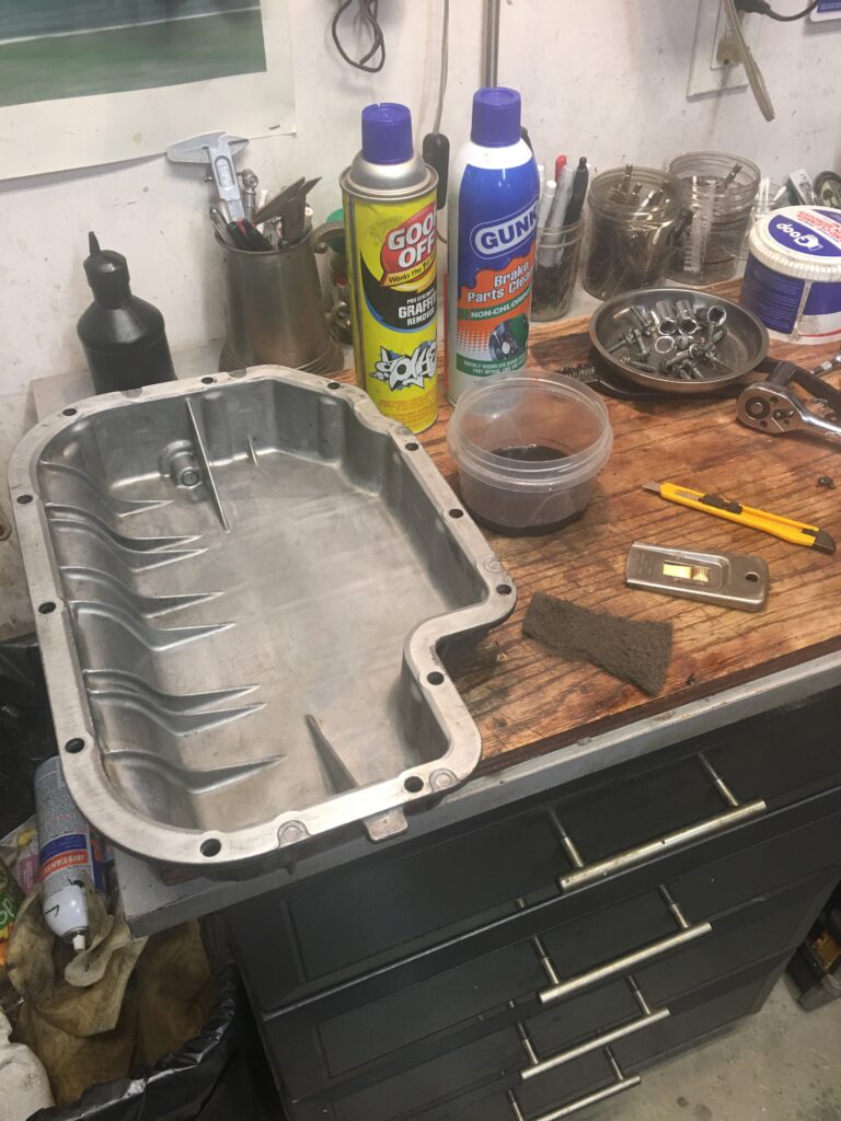
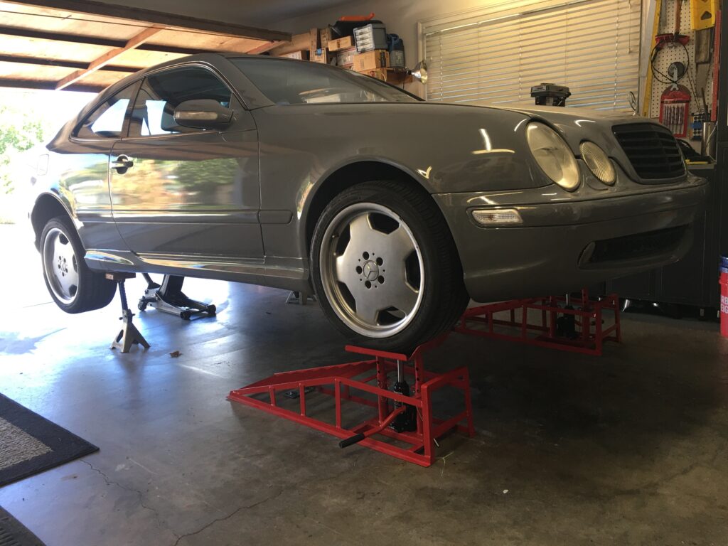
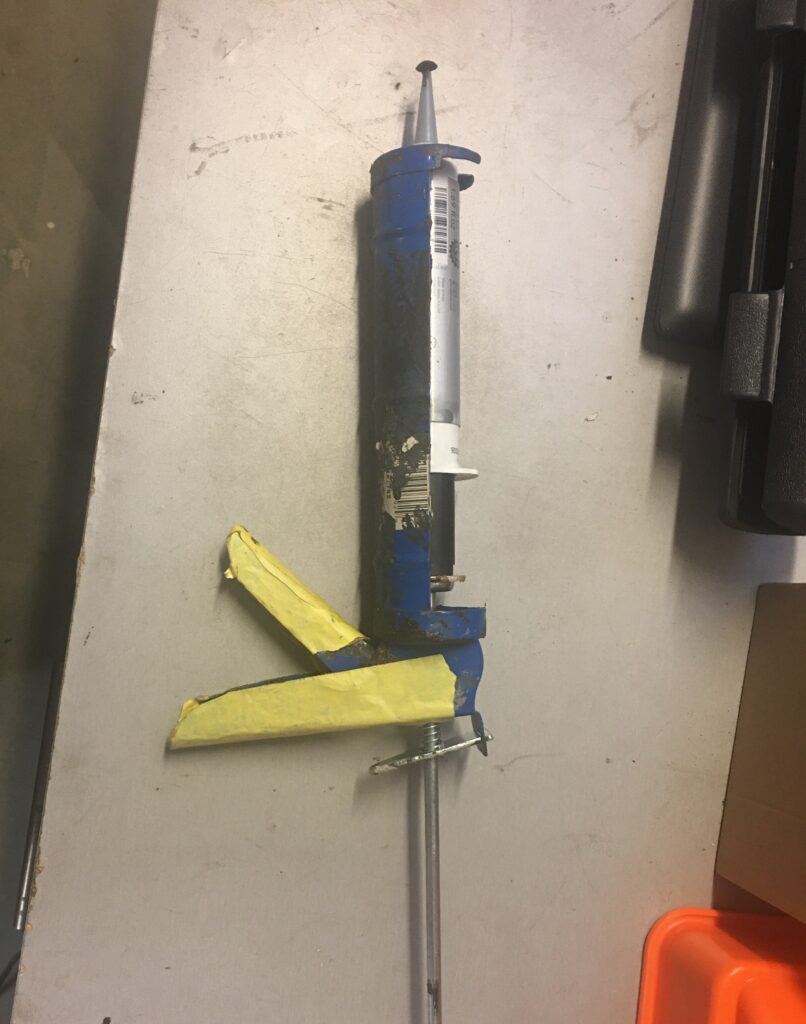
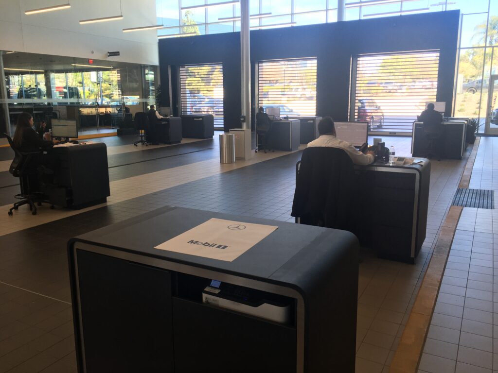
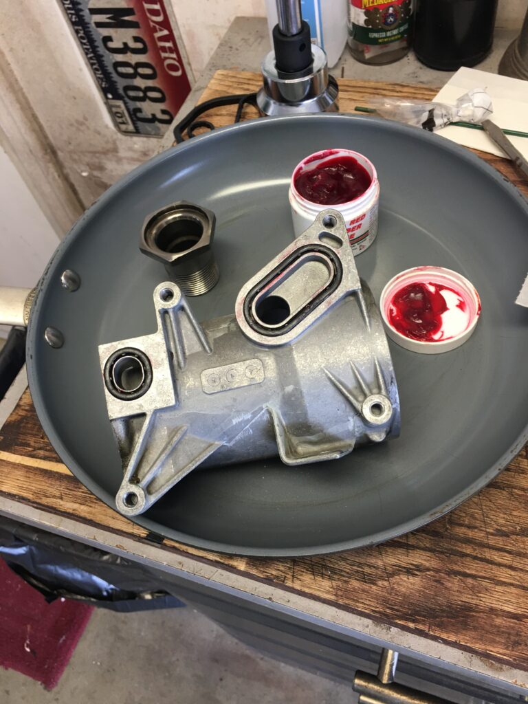
Essential toolsSway bar bracketFinally separatedOil level sensor goes through upper pan hereO-ring clearly not doing its jobNew sensor, attached by four E10 boltsLower pan cleaned up using razor blades, abrasive pad, and chemicalsThe upper pan also should be spotlessTake care cleaning the mating surfaces, I relied on Goof-Off and engine degreaser to loosen the old sealant then with a light touch used the straight razor blade and some Scotch-brite to ready the upper and lower pans for fresh sealant. Pans bolted back togetherThese ramps give me 20 inches of elbow room… less than $200The Mercedes sealant, Permatex Ultra-grey also does the jobThe bead should be a couple millimeters wide. The service drop-off area at Mercedes dealership. The sealant was twice as expensive here.
I do like the local Mercedes dealership, and they had taken care of our ML diesel before we swapped it for the Subaru Outback. It’s a great looking facility and of course the new cars on display are marvelous, but parts and service tend to be pricey. On the plus side, the parts department is totally open and honest about where the parts can be found at lower prices.
Now, with the oil filter housing and oil pan leaks addressed, hopefully the CLK55 engine is buttoned up for a few more miles. Next on the agenda is the transmission oil pan which seems to have sprung a leak.
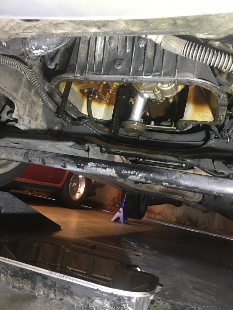
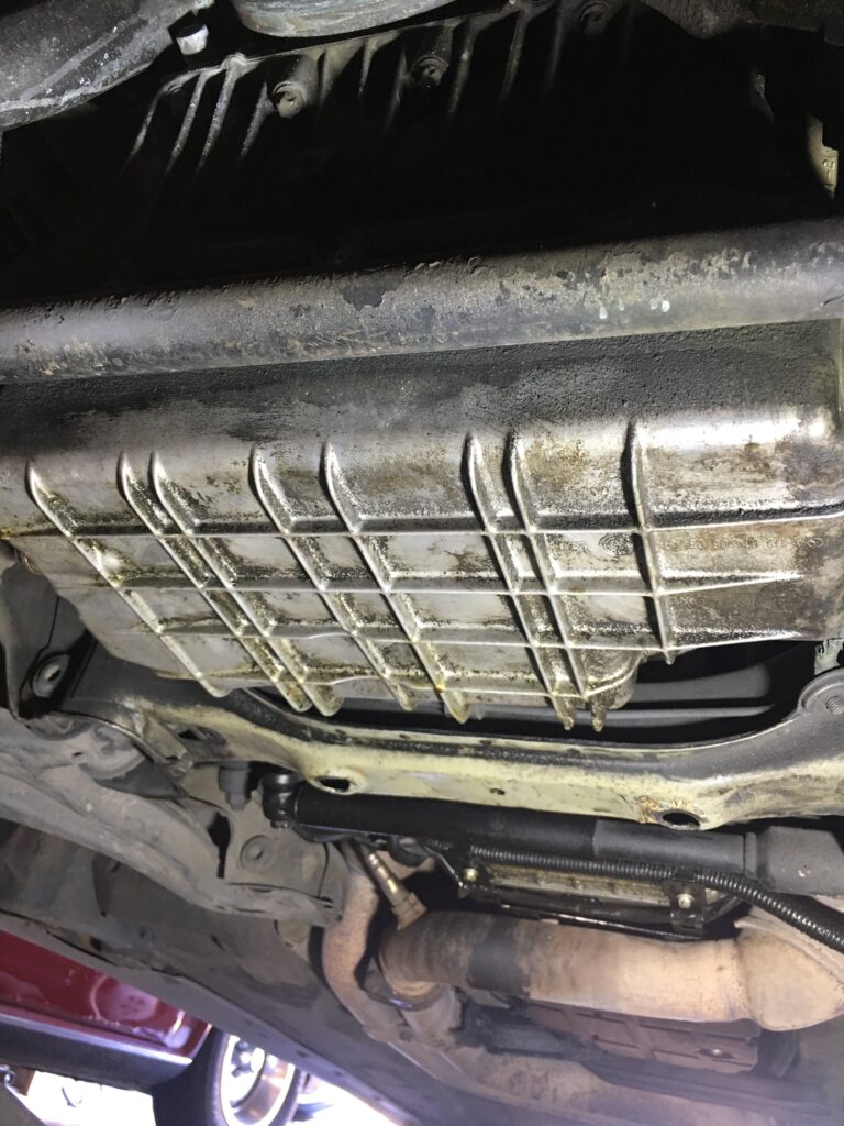
The 2001 CLK55 engine sprung a leak, evidenced one morning by a visible oil puddle behind the right front wheel. It was a narrow lake of oil, probably no more than a couple tablespoons, originating near the rear of the engine. After putting the car on ramps I crawled under to take a look.
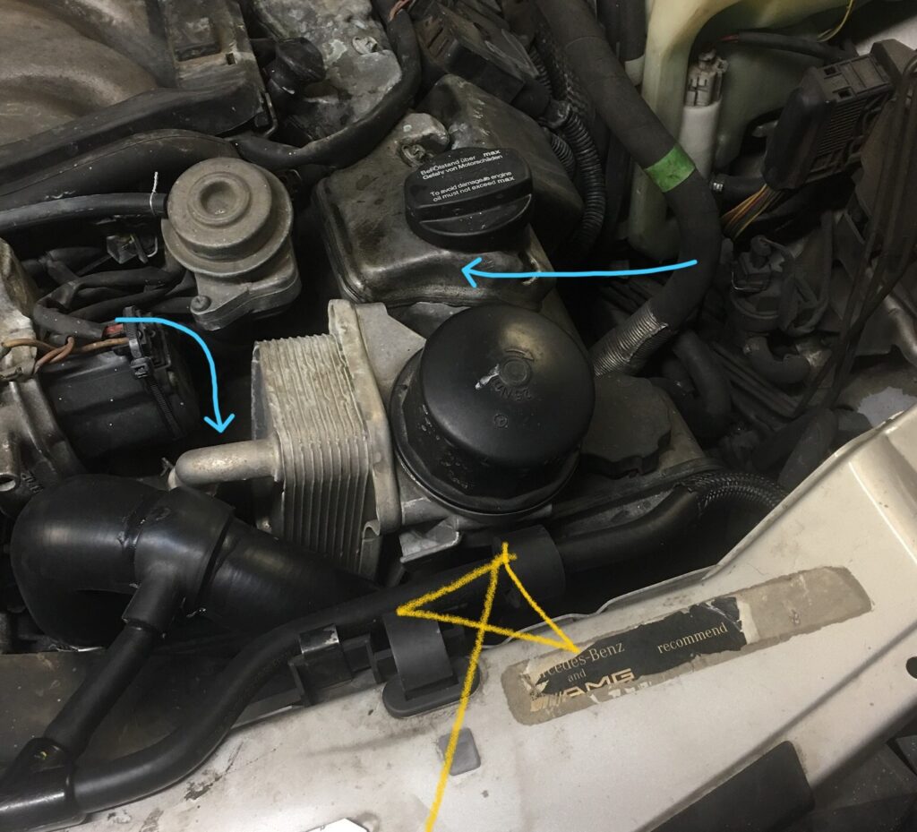
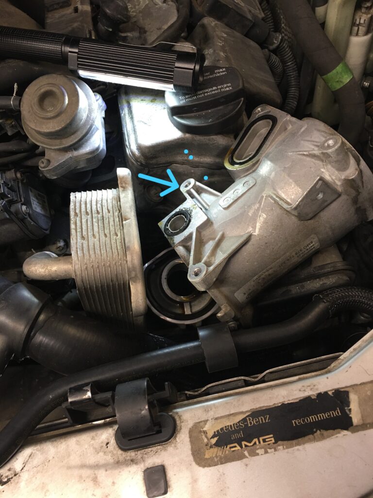
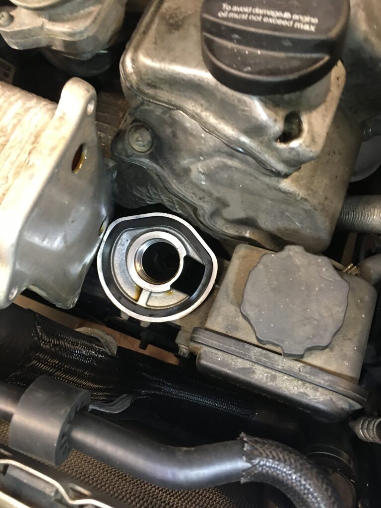
The evidenceThe likely sources, the oil filter housing and the oil filler cap. Yellow is pointing at filter housing that must be removed
I uploaded the photo and had a bit of consultation with ChatGPT as to the possible source of the leak, and eventually discovered there was oil on the front of the engine below the oil filter housing, and a bit near the oil filler cap.
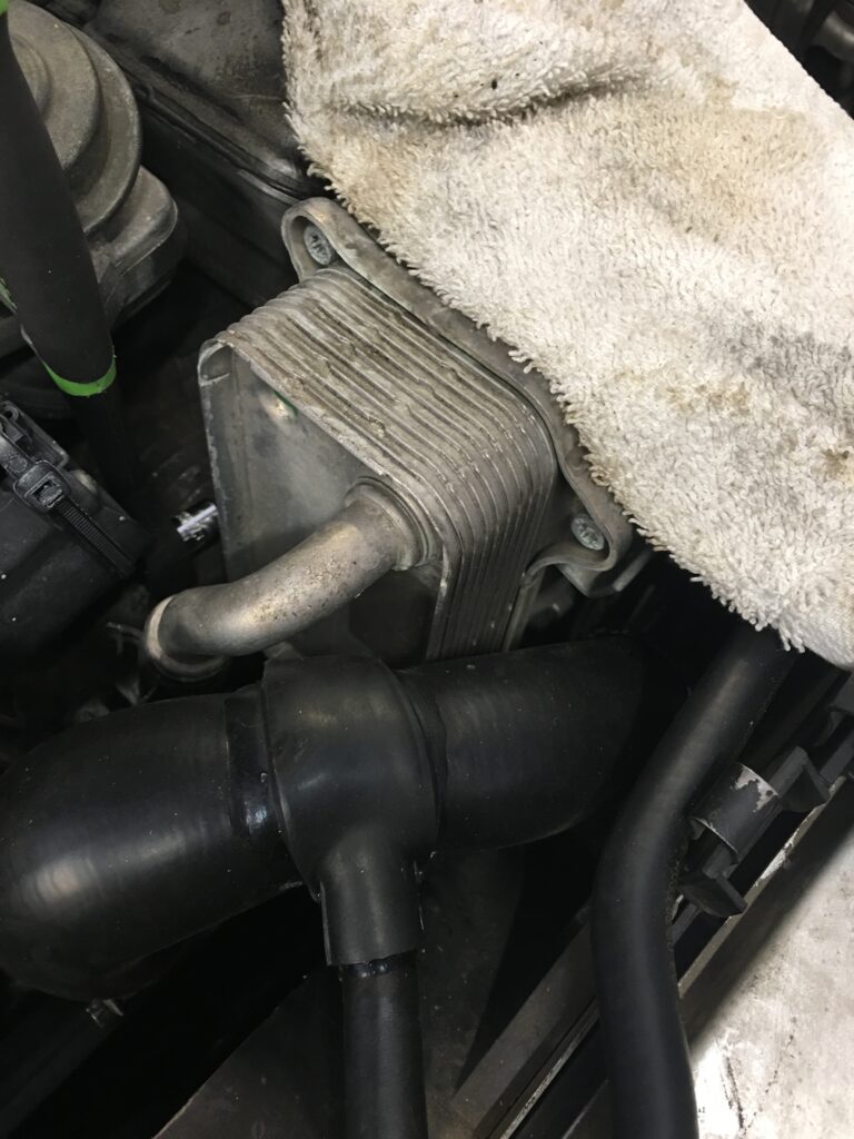
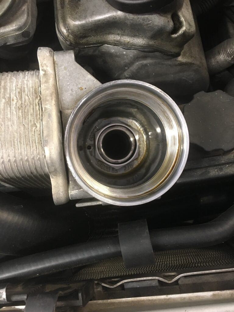
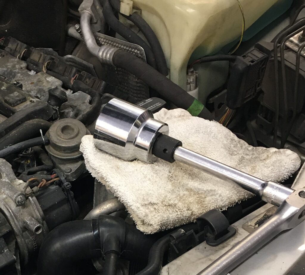
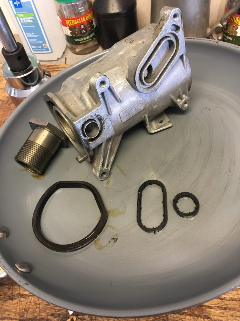
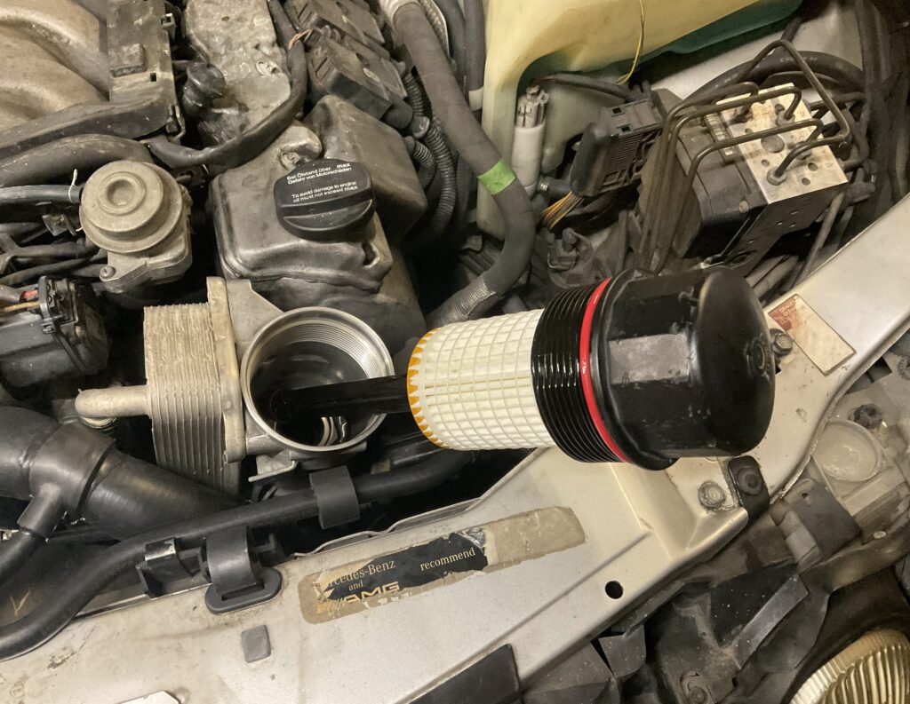
The yellow arrow points to the oil filter housing, which needed to be removed. I feared the worst, but found that it is a simple job. There are two rubber seals between the filter housing and the finned oil cooler, attached with four bolts removed with a T30 socket. The filter housing also has upper and lower halves, with a rubber seal between them. These are held together with a large hollow “bolt” that requires a 46 mm socket for removal.
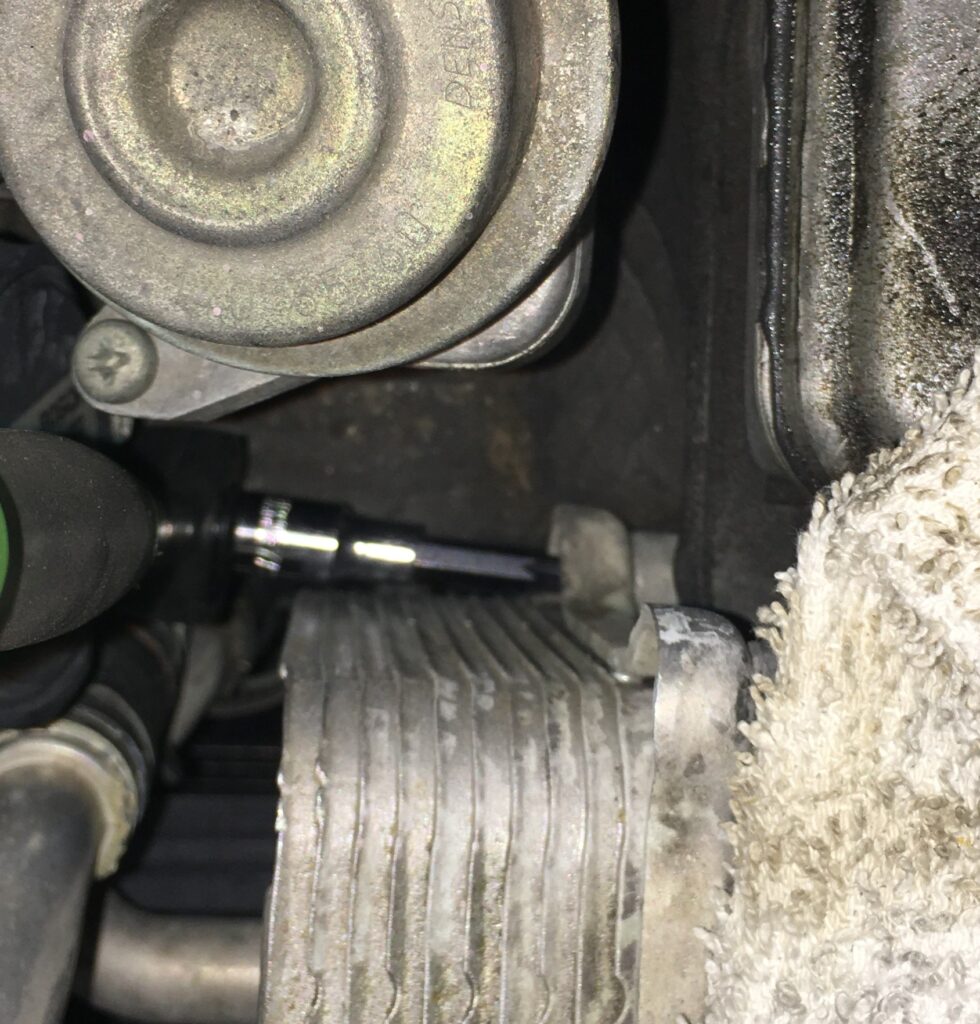
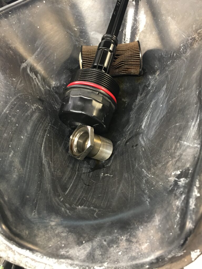
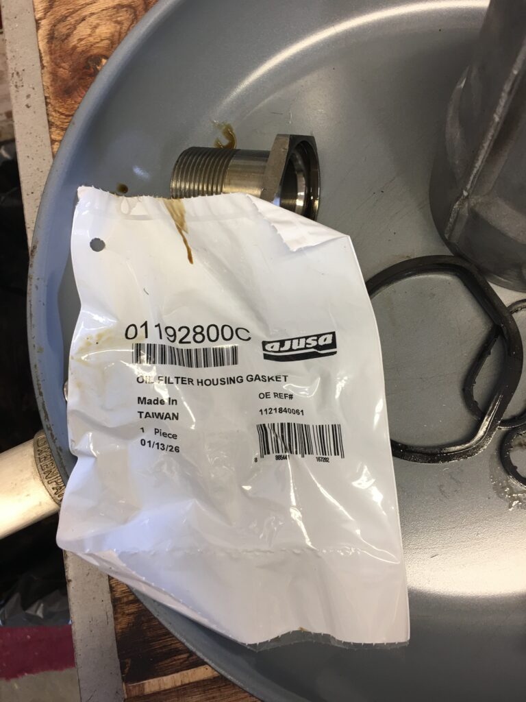
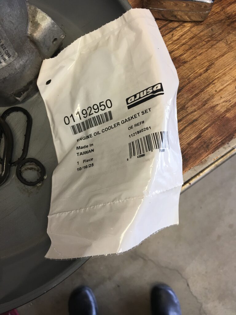
Four T30 socket bolts hold this cooler to the filter housingThis bolt gives the most grief, tight space for a ratchet down thereThat one!At bottom of housing, the 46 mm “bolt”I used a 1 13/16″ socket, which set me back $20 at Tractor SupplyThe torque spec is around 50 lb/ft, but it took two pulling on a 3 foot lever to break it loose. Old flattened, hard rubber sealsFound the seals online at AutozoneBottom seal lubed and in placeDitto for the two seals between housing and coolerNew filter going in, job nearly finishedAll buttoned up. After a couple long drives, not a drop of oil under the car!
When I first spotted the oil, I was tempted to donate the car to charity. However, what I feared would be a time consuming, difficult, and expensive repair turned out to be simple and straightforward.
I am an advocate of AI for help diagnosing car issues but ChatGPT was a bit off with this repair. First it insisted that I could replace the oil level sensor without removing the oil pan, telling me that it was removed from bottom of the pan, held by 3 bolts. NOT!
And then it was pretty clueless about the 46 mm bolt securing the upper half of the filter housing to the lower half that bolts to the engine block. By providing photos and working through it, I’m hoping it got a little smarter.
No plastic plate secured with 3 bolts down hereThis is the oil level sensor, not critical, but annoyingSeen here roughly above the drain plug, it’s accessed after removing the oil pan
Next up, in a few thousand miles, replacing that oil level sensor. And then… fixing the ABS/ESP/BAS fault, which means having the pump rebuilt.
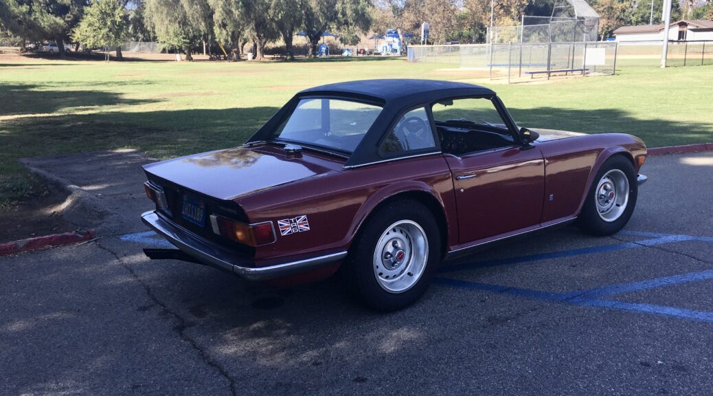
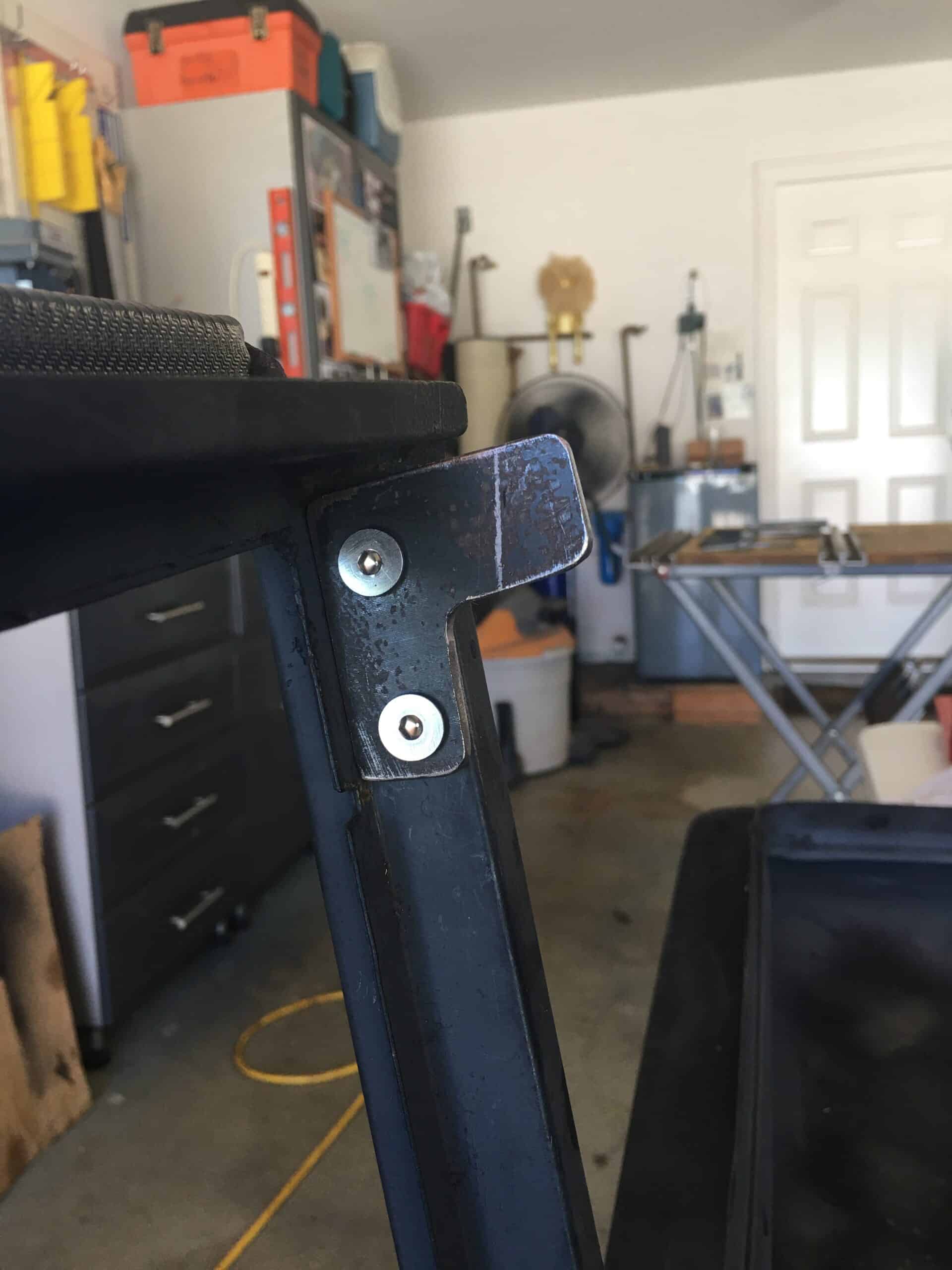
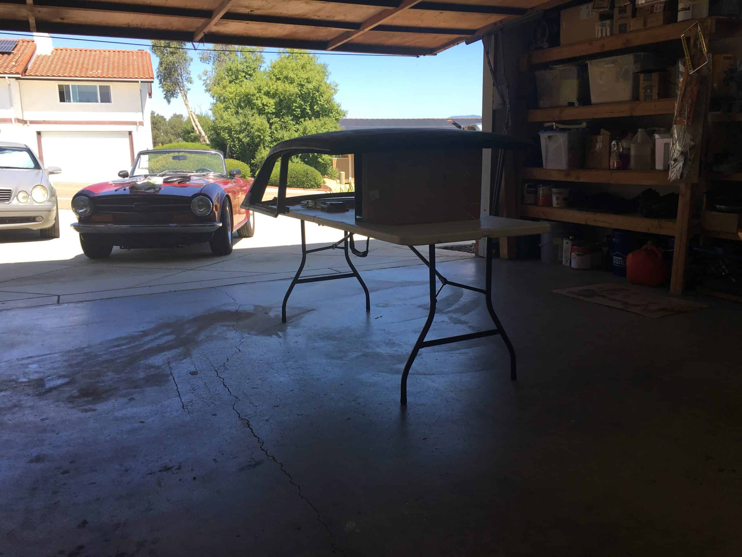
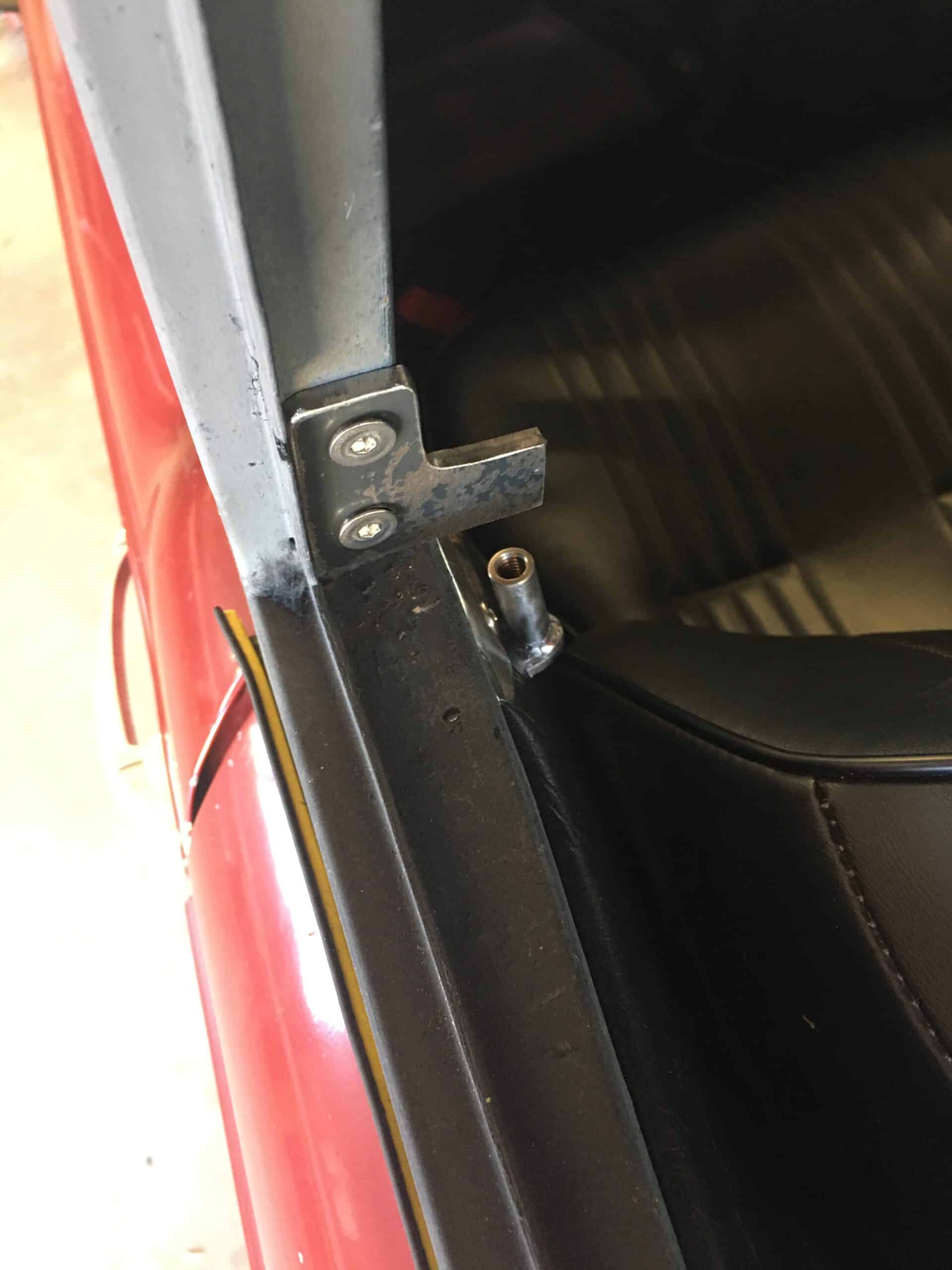
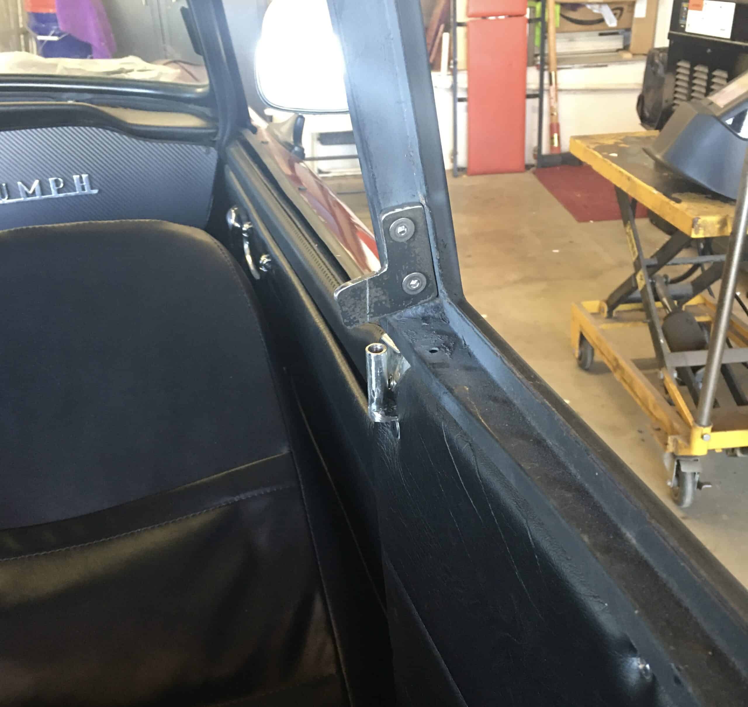
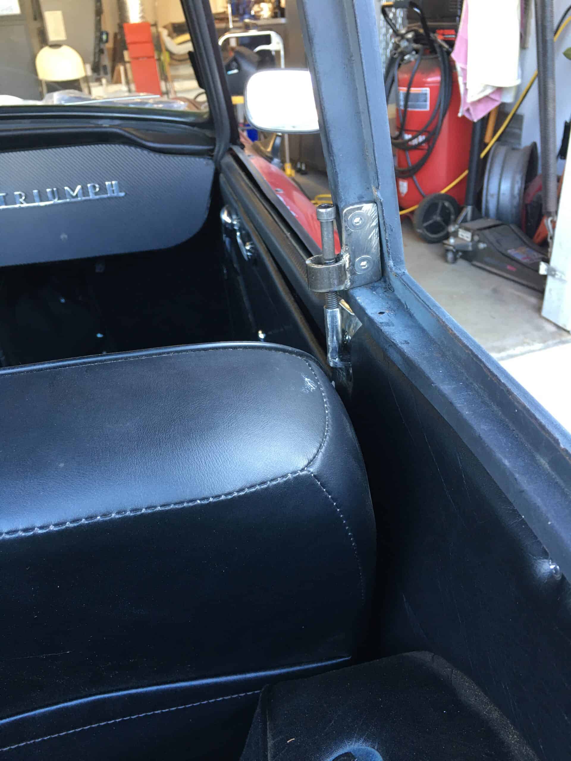
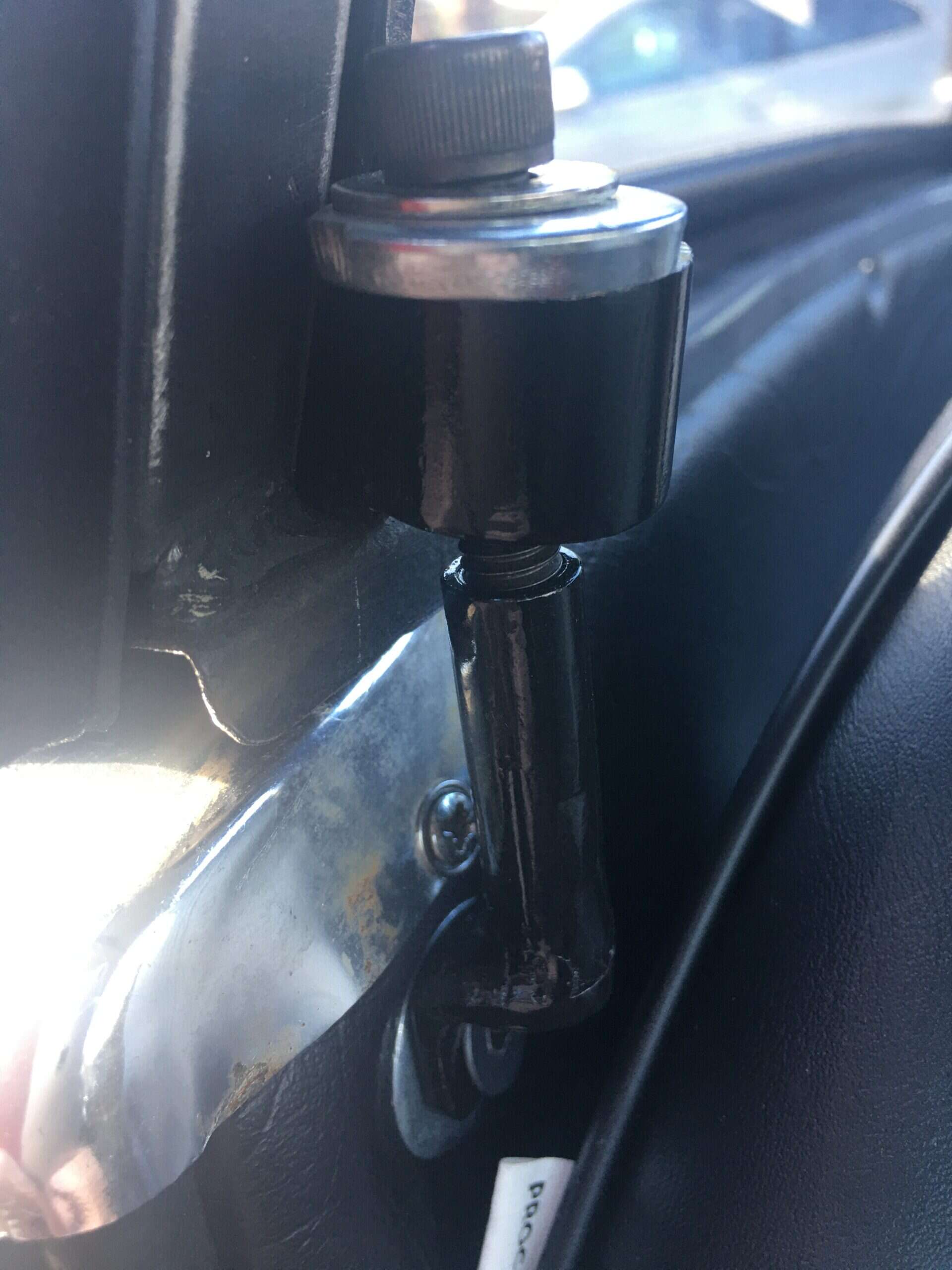
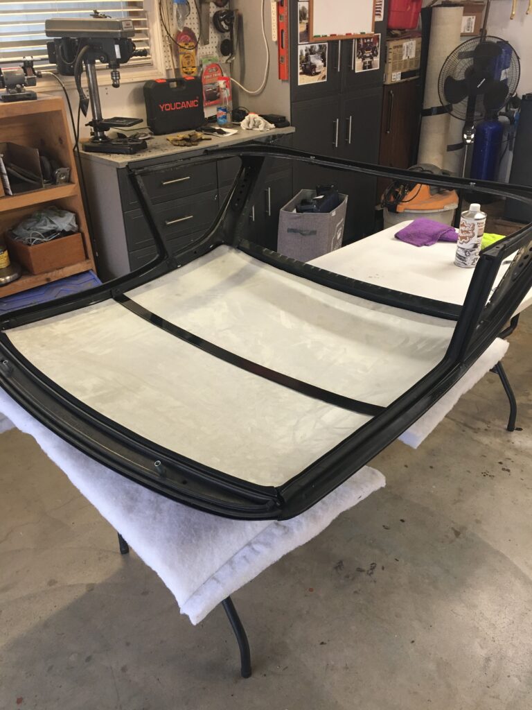
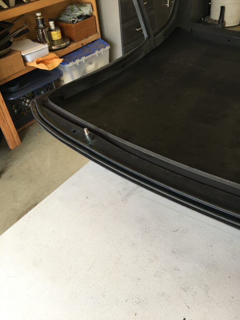
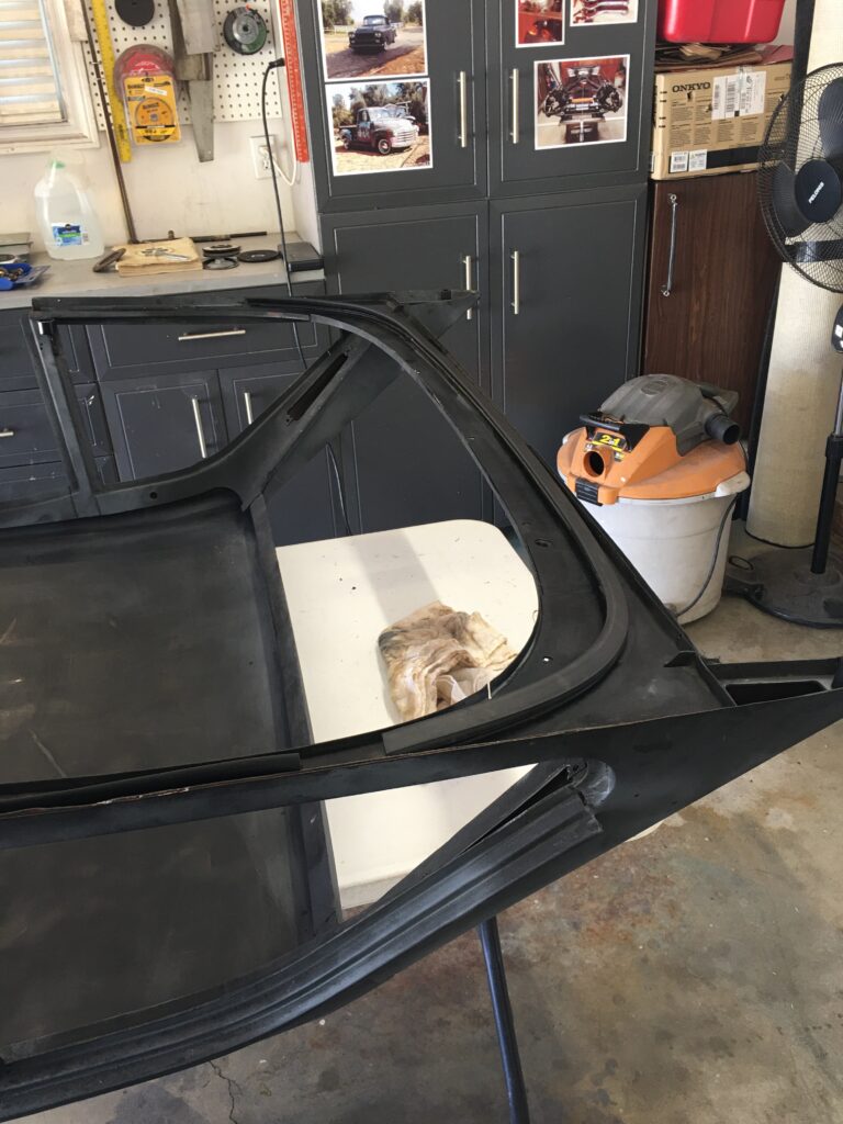
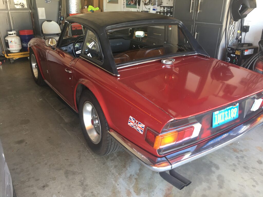
I have been half-heartedly looking for a factory hardtop for the Six, and this summer I lucked out and found one within an hour drive. It was a bare top but included all windows – in excellent shape – and some but not all of the rubber. The paint looks like rattle-can flat black and there are a couple very slight dents front and center, hardly noticeable now but which would need fixing prior to painting. I had to make the mounting brackets at the B-pillar, and I added insulation and headliner, as shown in the photos.
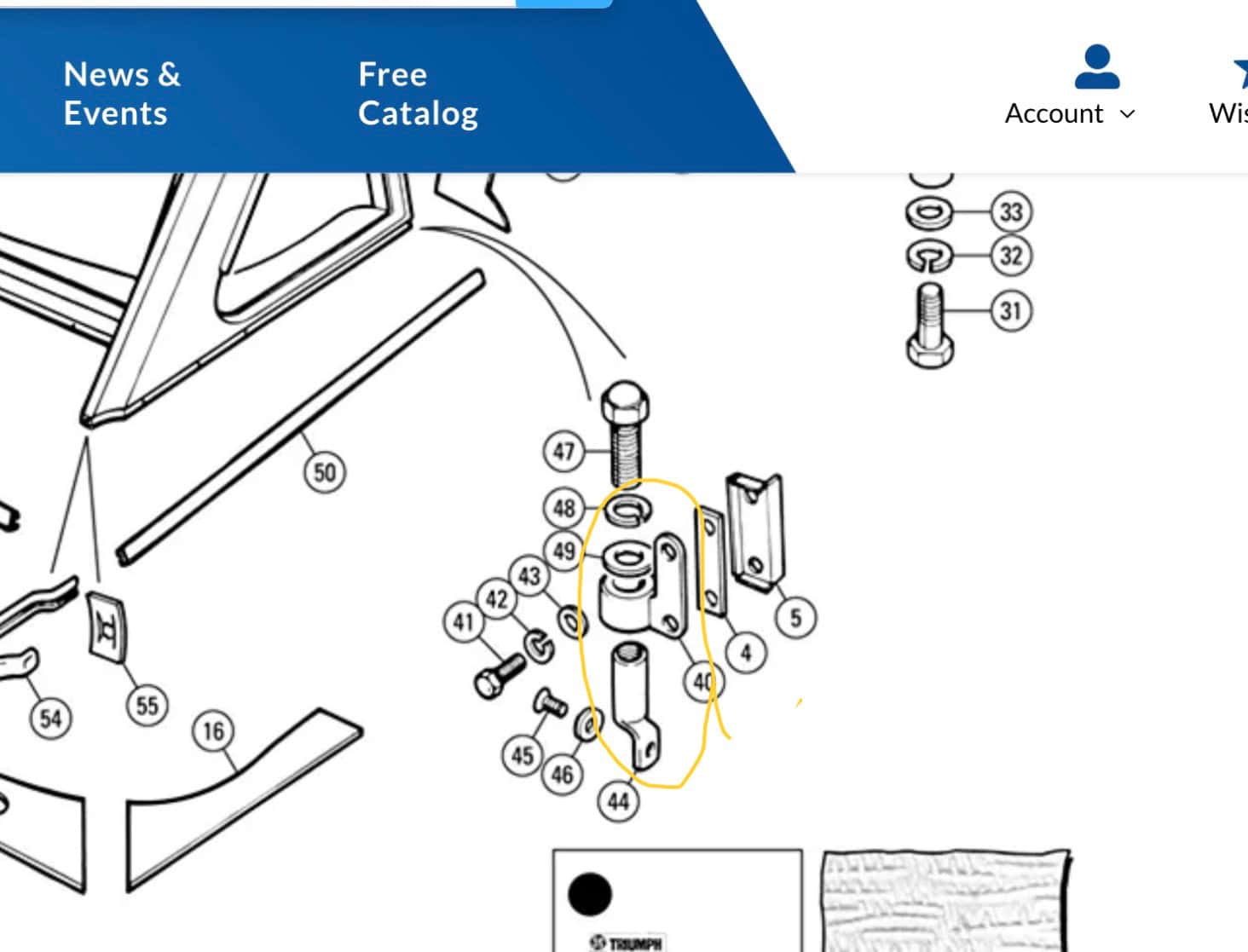
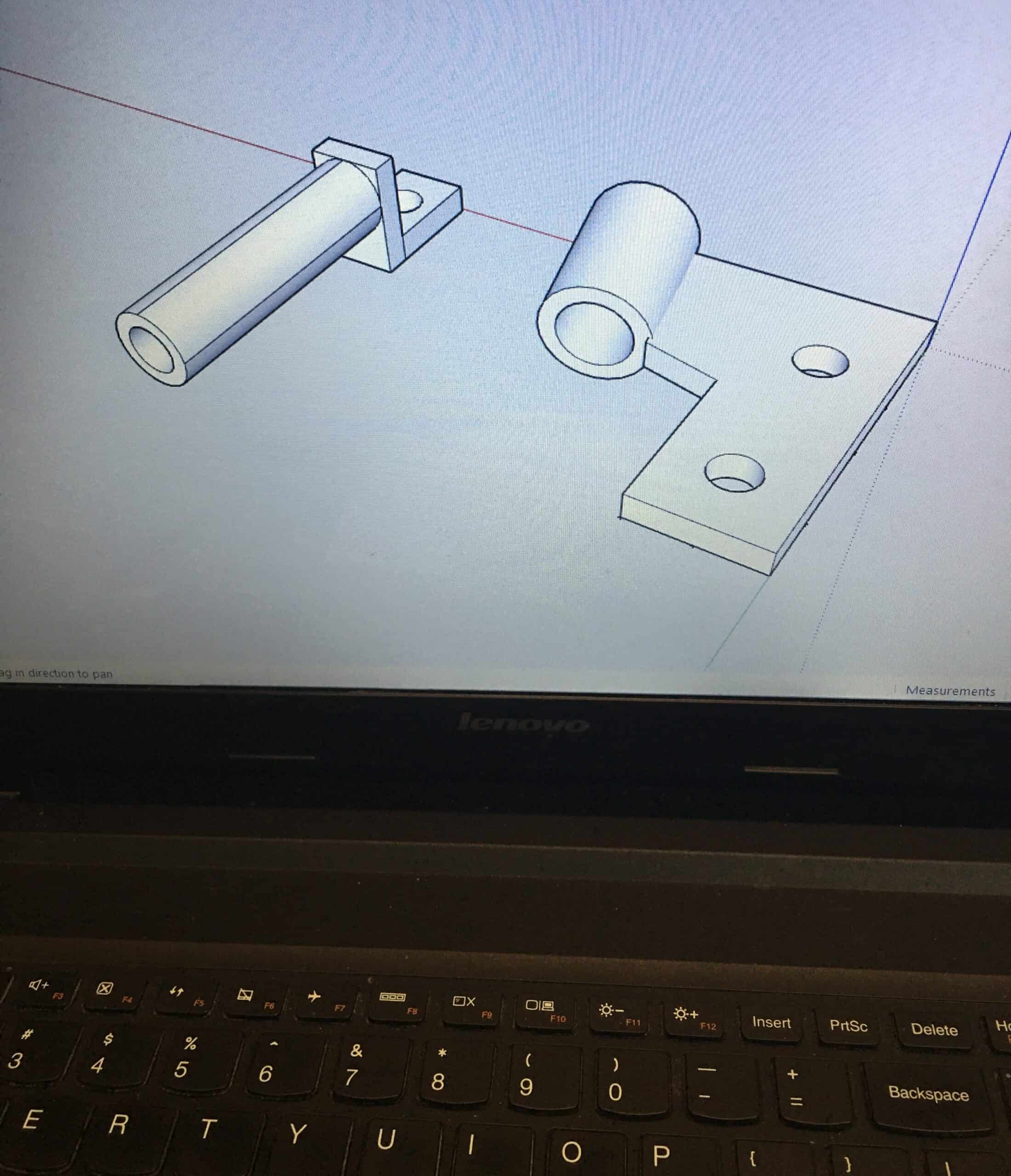
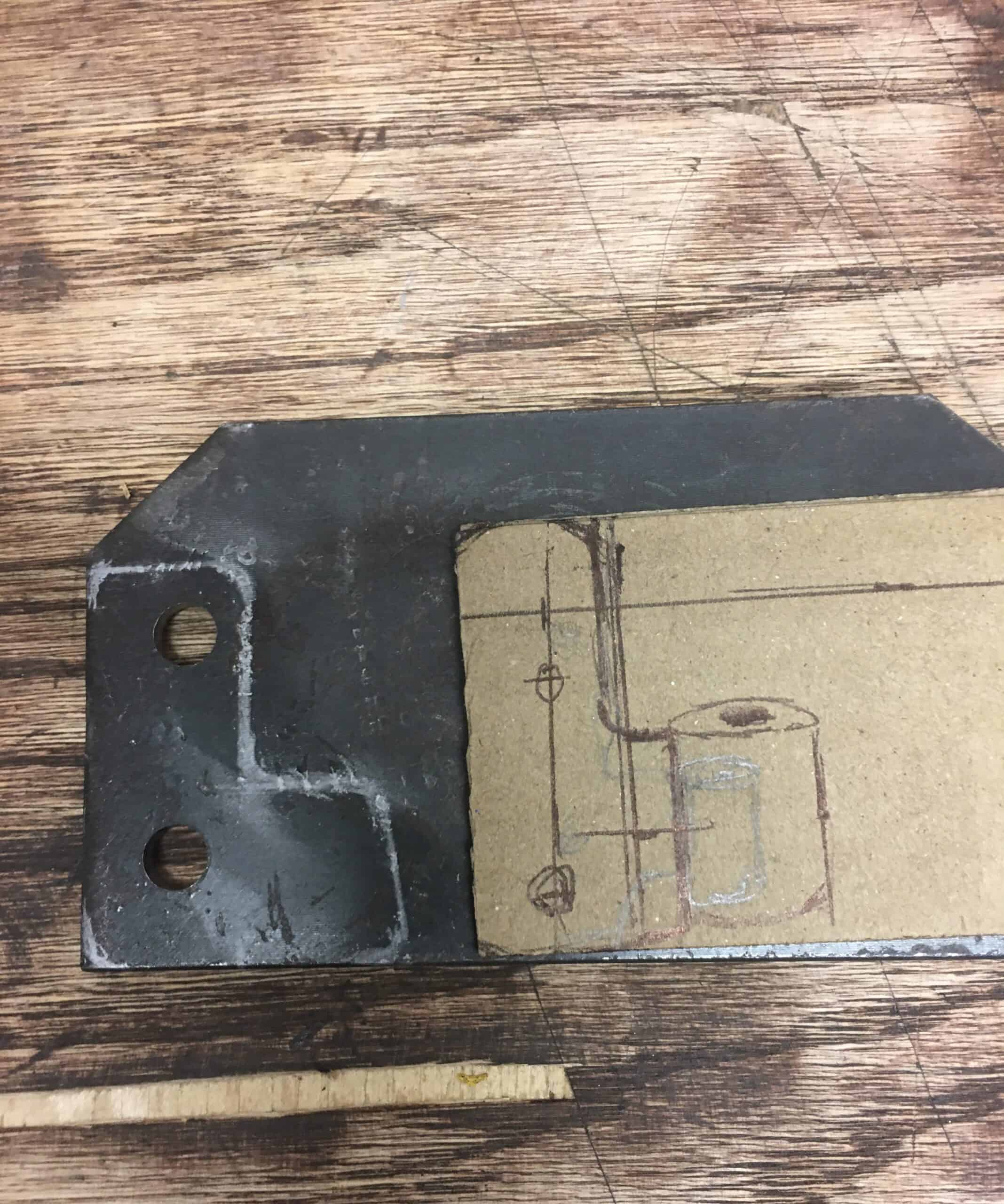
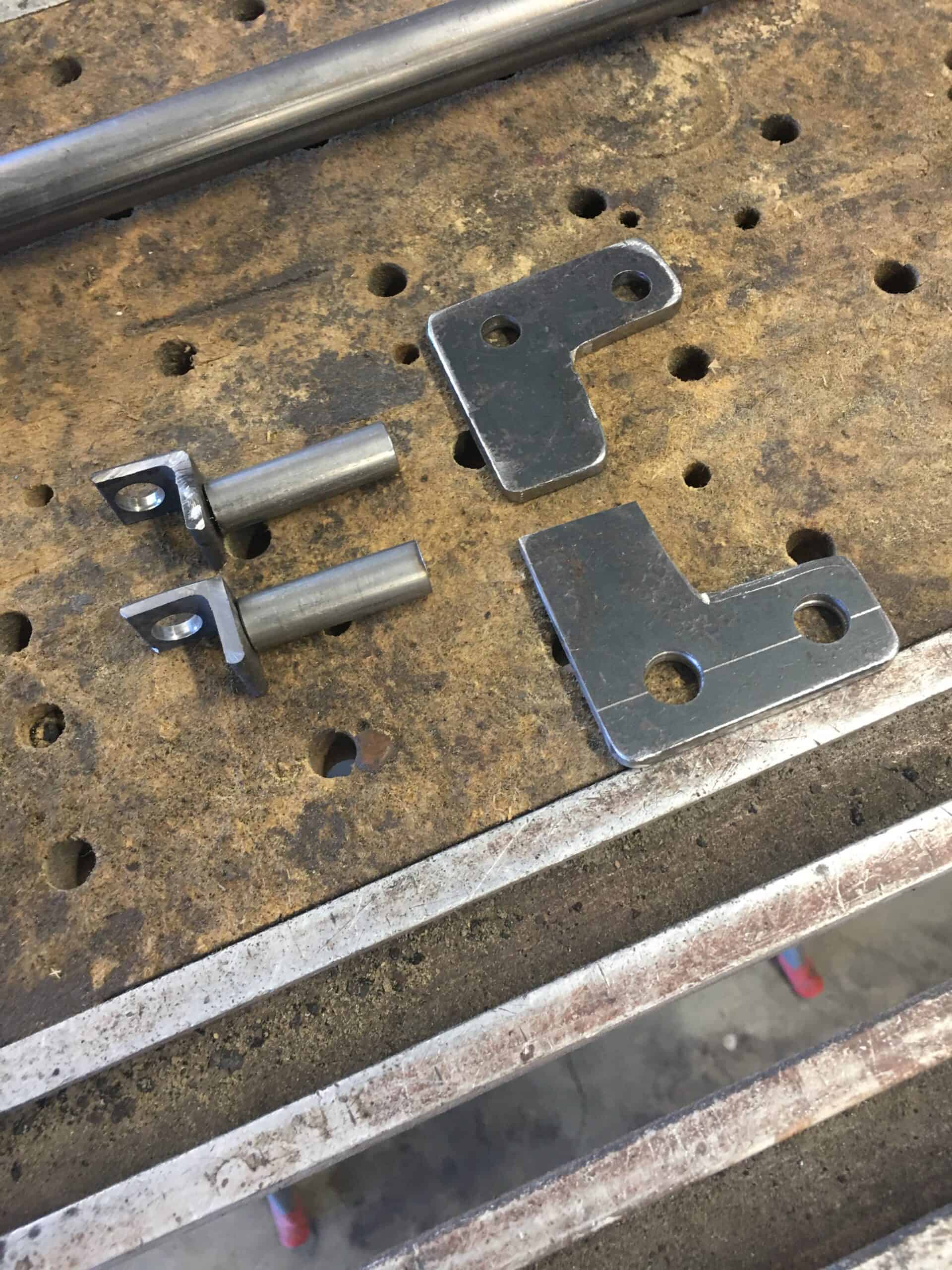
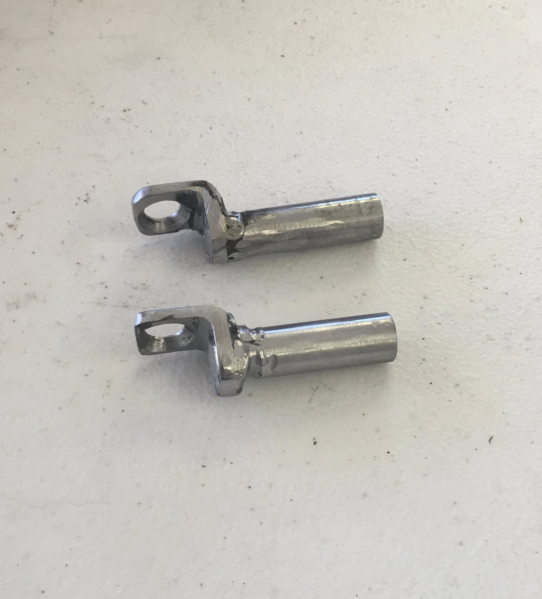
First, I made the B post brackets, which were either unavailable or crazy expensive.
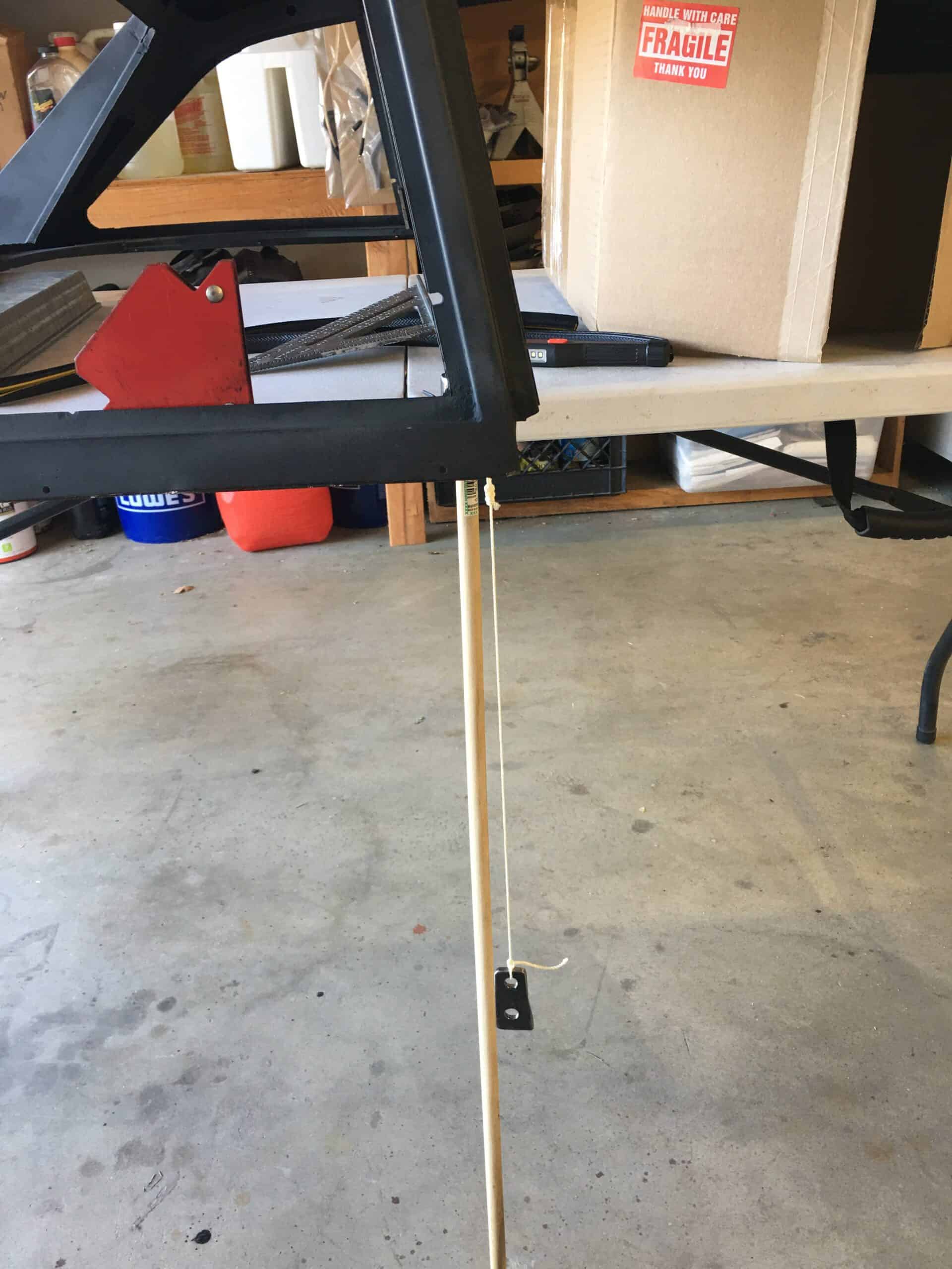
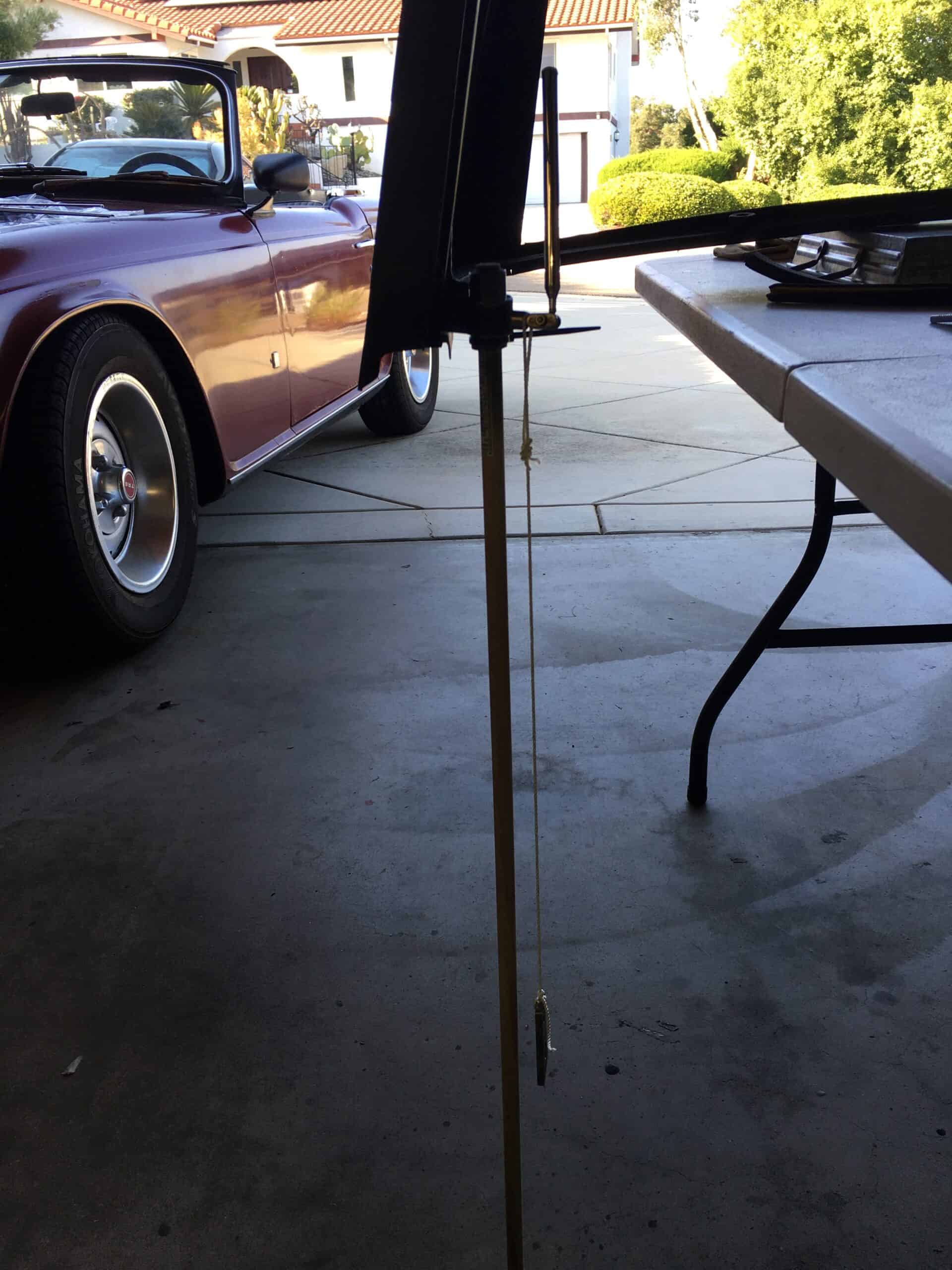
B post brackets were unobtaniumSketchUp to visualize what I needed to makeTime to cut some metal, 3/16th steelAngle iron, internally threaded tube, and the 3/16th platesWelds are a bit rough because I didn’t use our gas shielded rig at the barn, but good enoughTest fittingGetting the top level for the next stepPlumb bobbing, there are two angles to deal with… just trying to get close.The B-post leans toward center of the car and leans toward the rear, so we are plumbobbulating. Your new word for the day.Eye-ballingDrawing lines and eye-balling againA little black paint, a couple washers, and we’re doneFinished B-post bracket, not perfectly aligned, but the top is easy to install and it’s not going to fly off
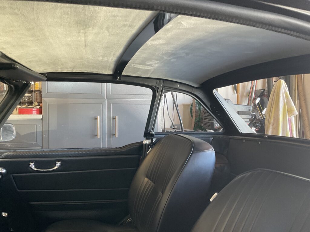
Although I’m not finishing the top at this time, I did want to experience enclosed driving through the winter, and decided to try and make it quiet with insulation and headliner.
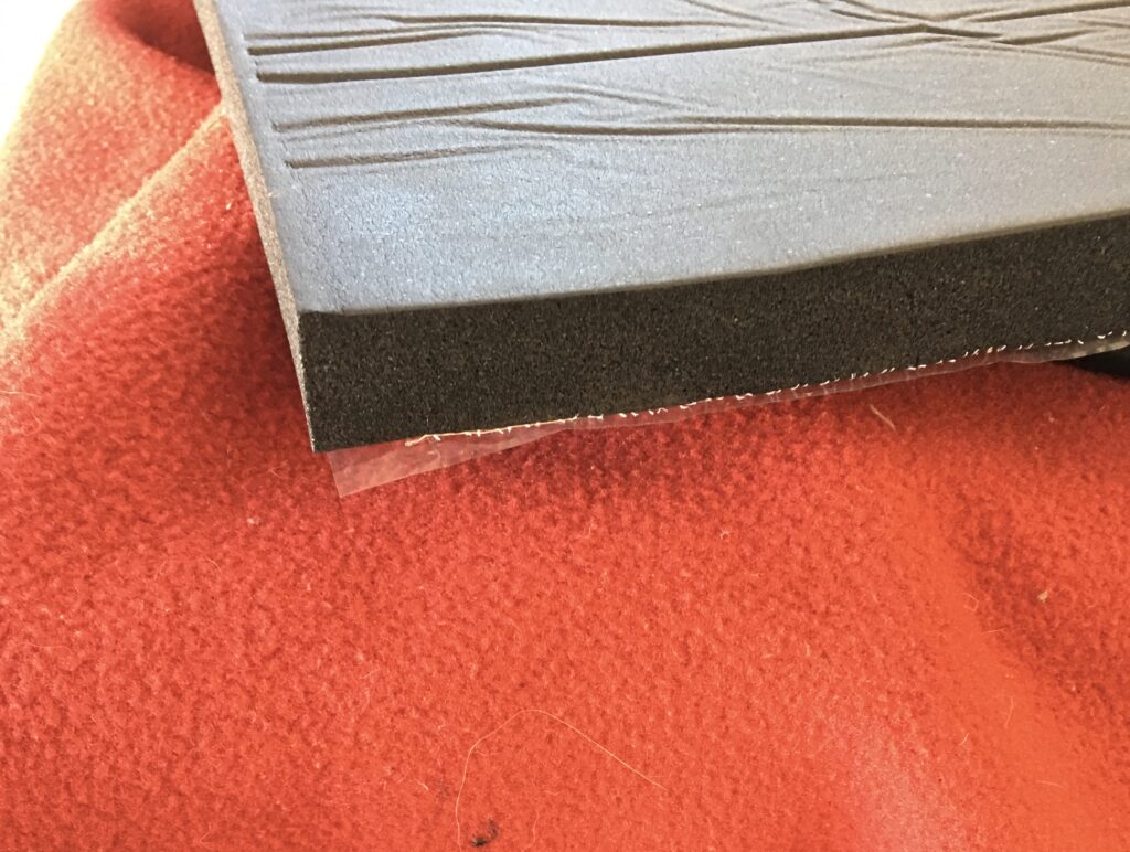
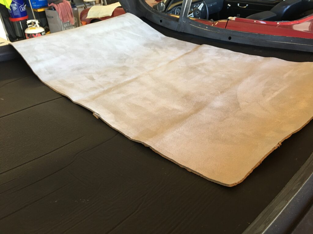
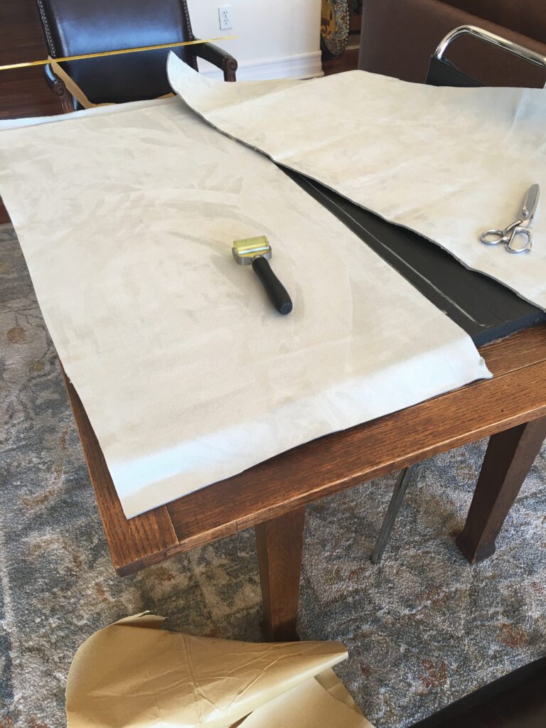
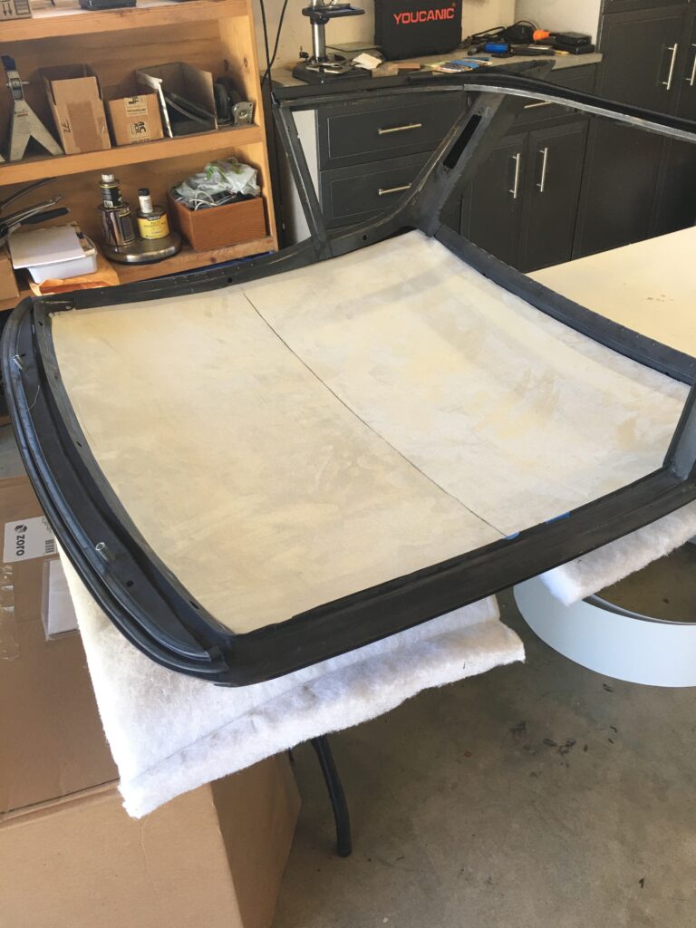
Adhesive backed 3/4 inch foamNice soft suede, 1/4 inch foam, also adhesive backedTest fitting the insulationGetting set to cut the headliner to fit the 3/4 insulationThe suede headliner I selected required a two-piece approachAll stuck togetherMetal rib covers the seamNot a bad result, with a total of an inch insulation, around $100 for the materials
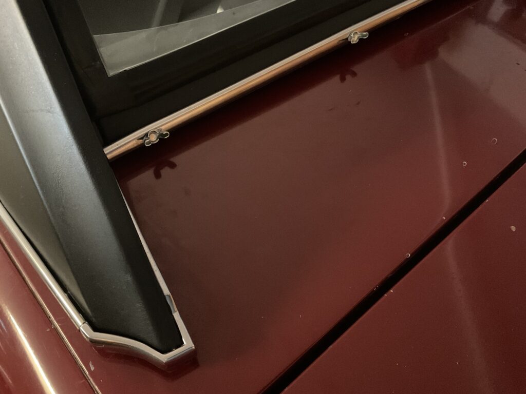
The final steps included installation of the seals, the glass, and the chrome trim. I chose to have the glass done by Grace Auto Glass, as I had used them previously when assembling the windshield a few years ago.
It seemed to me there were some conflicting and incorrect comments re installing the seal between the hardtop and the windshield. So, quoting the official Fitting Instructions for Item 11, the Hardtop to Windshield seal, this is the process I followed…
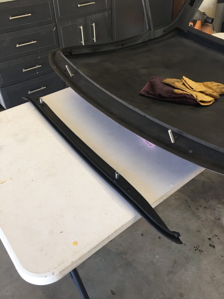
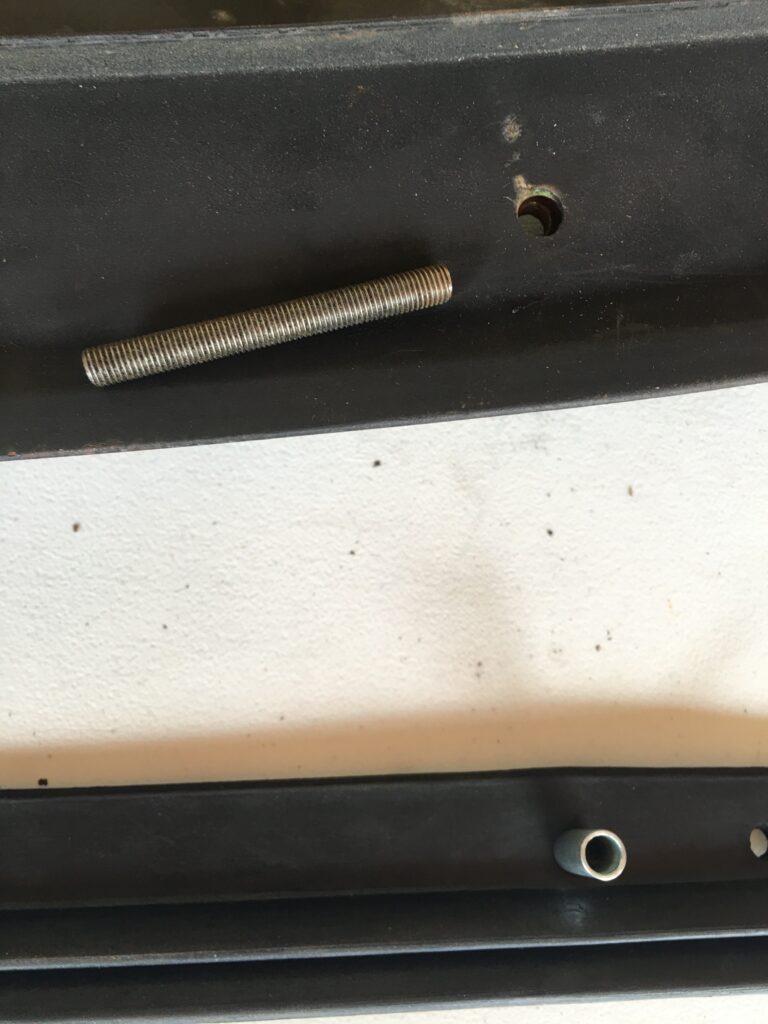
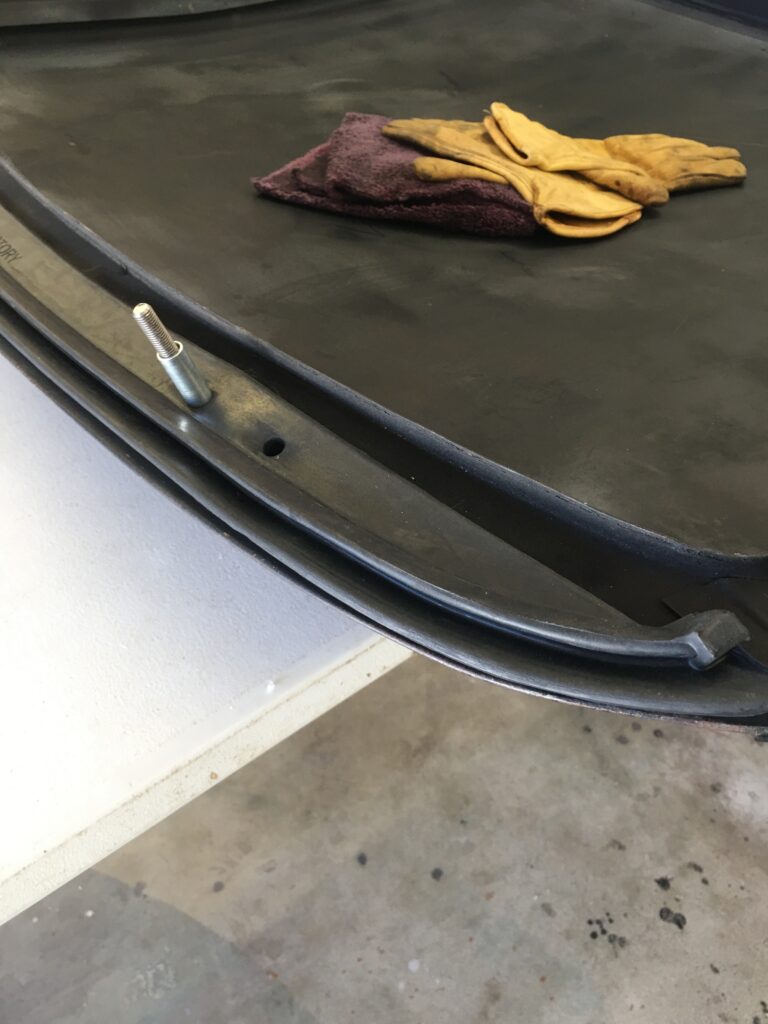
Place the rubber with flat side facing upwards and apply adhesive to the complete area of the flat surface. Insert distance tubes through the inner holes of the rubber. Screw a 5/16 inch “slave” stud finger tight to each of the two weld nuts in the header panel of the Hard Top, in order to locate the exact position of the rubber. Position the rubber to header rail and press down firmly to ensure satisfactory bond. Remove “slave” studs.
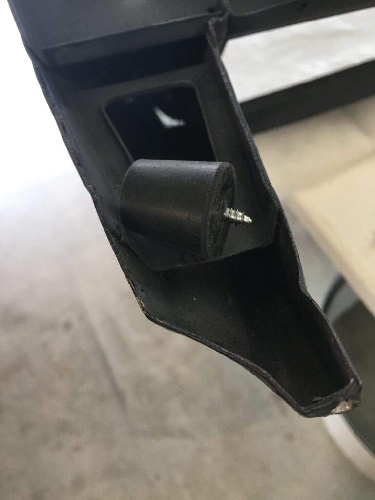
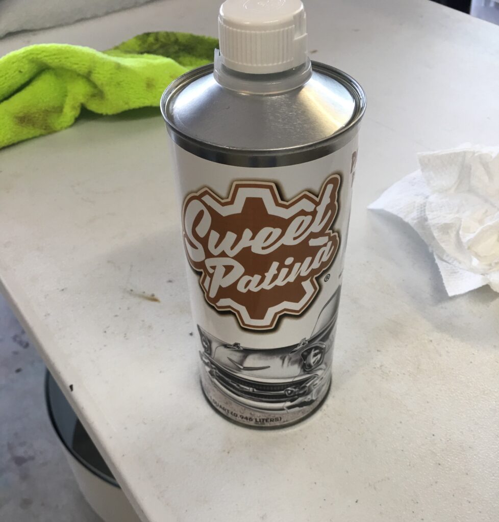
HT to WS seal, studs finger tight into captive nuts, distance pieces inserted through the rubber seal, ready to apply adhesive5/16 – 18 studsGlued, but I did not apply adhesive across the entire seal, just from a few inches inboard of the distance pieces and out to the endsGlued down, and ready to unscrew the “slave” studsThis seal was a bit tricky, but after cleaning up the channel, and slightly opening up the channel around the sweeping 90 degree turn, it slid in pretty easily. I then tightened the channel up a bit with pliersTrip to Ace Hardware for these stoppers that I drilled through to use as the buffers between HT and rear deckInstalled, with glass and chrome!I could not get the long chrome piece to stay on the rivets, so I got creative. Oh wellSince I am holding off on painting the top (and the entire car) I applied Sweet Patina on the top to offer a little protection against the elements this winter.
The Six actually seems like a real car now rather than a toy, but I’m pretty sure that come next spring the hardtop will be coming back off. For now, I will experience cozy comfort through the San Diego “winter.”
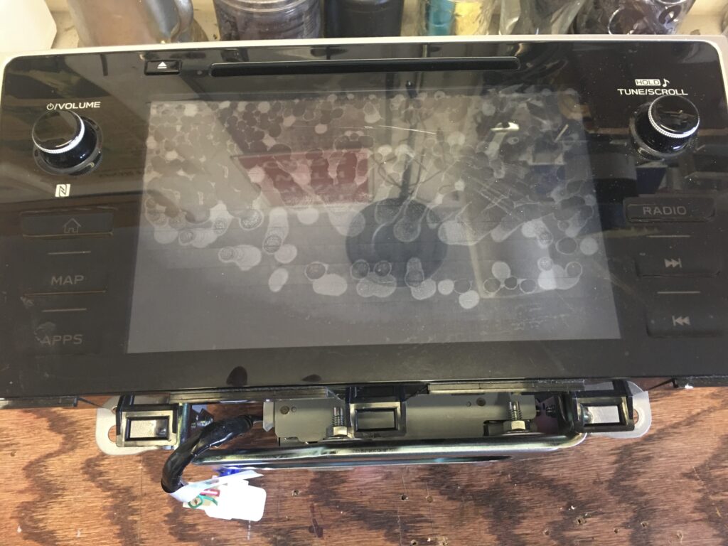
If you own a 2018 or 2019 Subaru, either the Outback or Legacy, with the Harmon Kardon radio, it’s likely you have experienced the head unit failure. The radio had already been swapped once by the dealer while under warranty, but this time the warranty had expired. Not only was the dealer replacement going to be ridiculously expensive, but the deluge of customers with the problem meant that wait times were indefinite.
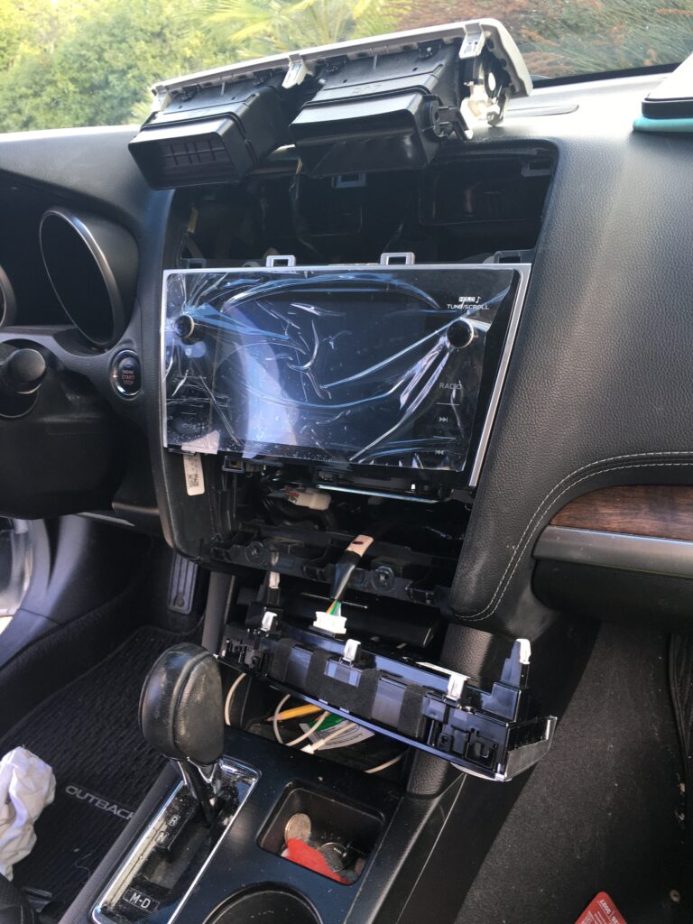
The delamination problem
The next option we considered was an after market radio, but the units I looked at, priced at around $1200 and up, all seemed to require some compromise… back up camera differences, steering wheel control glitches, etc. Then, luckily, I stumbled upon the information that this was just an issue with the touch screen. That’s why the screen appeared to have finger prints all over it and why the radio had a mind of it’s own, the head unit failure meant nothing was working.
Kinetic Vehicles solved everything.
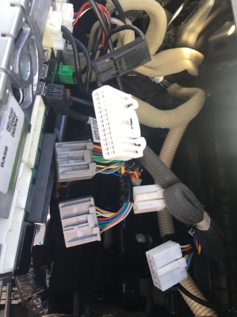
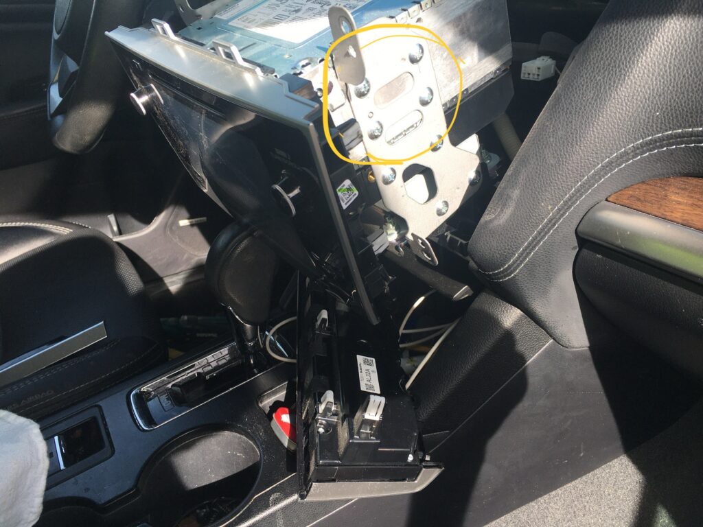
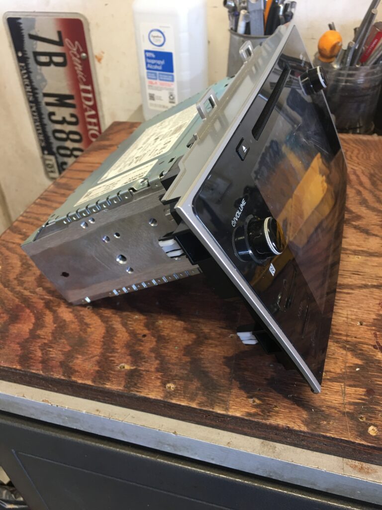
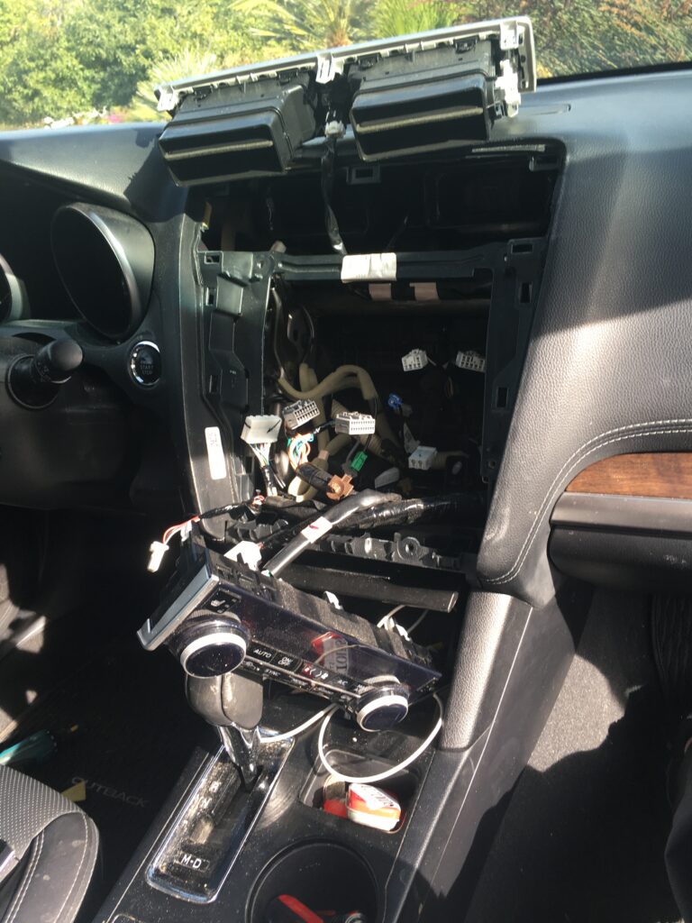
Solution – swap out the touchscreenEverything in back just unpluugsPush down tabs ro release plugsFour screws each side release radio from chassisSend this to Kinetic VehiclesThe vents and A/C controls had to be moved out of the wayYou’ll drive around like this while Kinetic has the radioRadio getting plugged back inInstalledEverything working perfectlyIncluding the backup camera
This video from Kinetic Vehicles shows how…
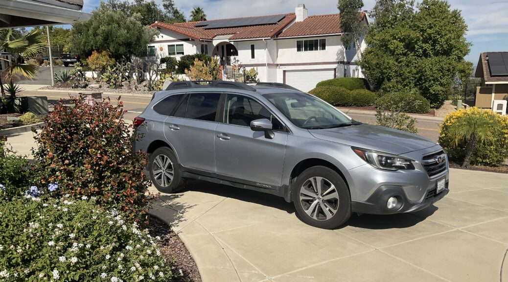
I should add this about our ’18 Outback… it’s been a great car. We loved the ML diesel but the Outback is the better car because of technology eleven years advanced from the Mercedes. The ML diesel was torquey and you felt a nice surge with the turbo. But the Subaru 3.6 flat six has 270 horsepower and is probably a bit faster. My favorite feature, by far, is the adaptive cruise control. For me it’s a much more relaxed way of driving. And I also appreciate cameras warning me about cars alongside, the bright yellow warning lights on the mirrors are hard to miss.
Now that the head unit is repaired, it’s good as new.
My 2001 Mercedes CLK coupe went into “limp home” mode on a couple recent drives, fortunately just a couple blocks from home each time, stuck in third gear. After the first instance, the car stayed parked in the garage for a day. Full of optimism I took it for another drive, but it limped home again. I was fairly certain that the problem was in the transmission conductor plate, but to be sure I wanted to scan the TCM module.
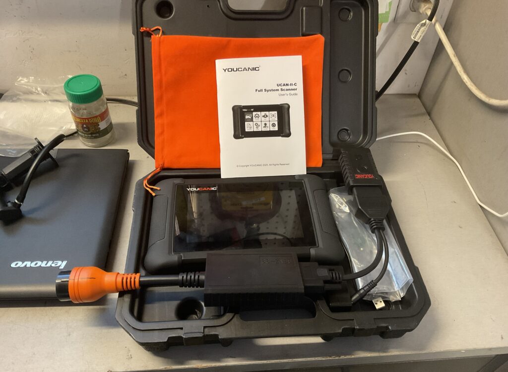
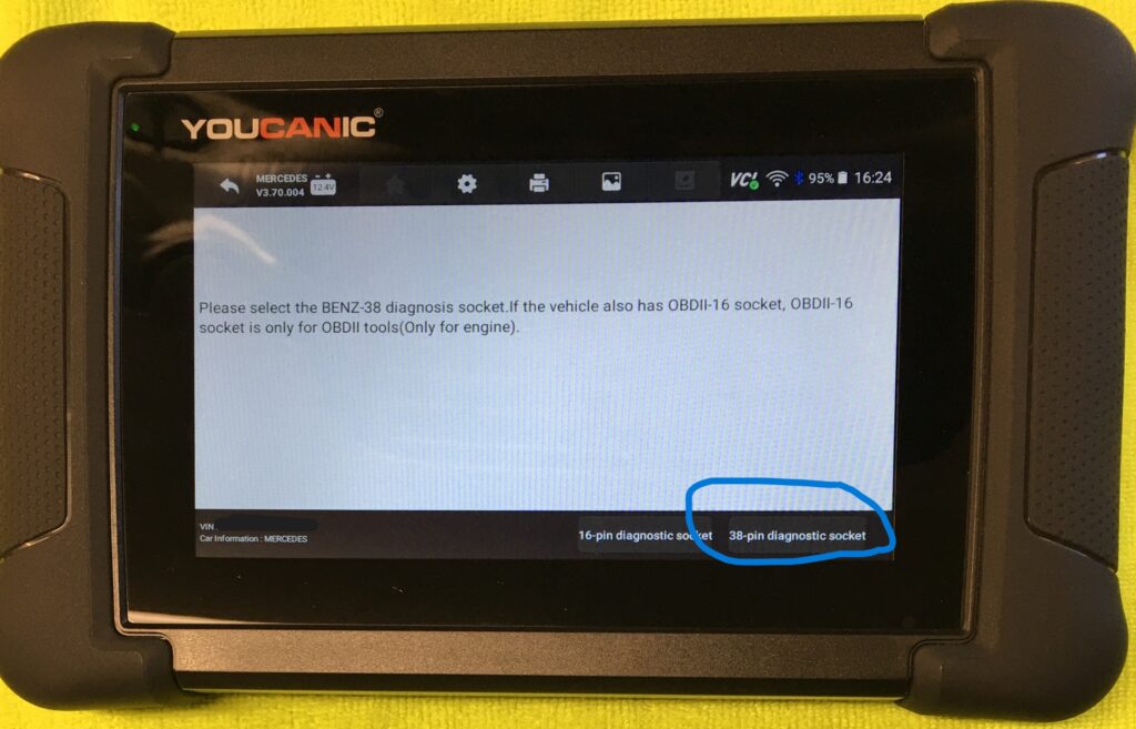
Youcanic scanner with the 38 pin Mercedes accessory
For many Mercedes cars from 1994 to 2002 this meant hooking up to the 38 pin connector. After checking with a local independent Euro car shop and being quoted $200 to have all the modules read, I decided to purchase the Youcanic UCAN-II-C, plus their 38 pin Mercedes adapter. I purchased an “open box” unit directly from Youcanic for $370, plus $30 for the adapter.
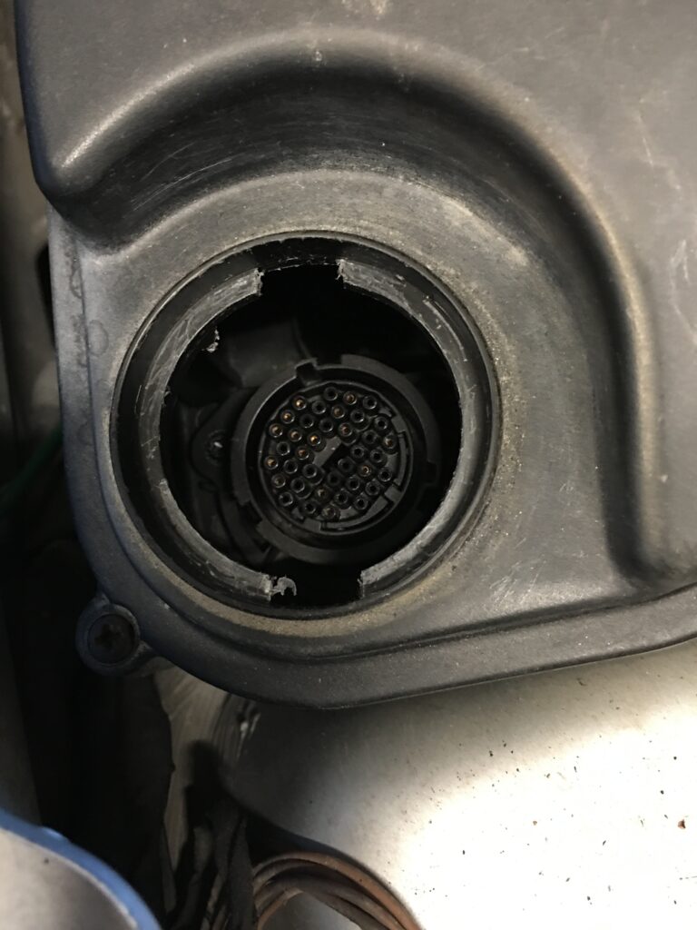
UCAN with adapter at topThe 38 pin plugLocated here on the CLKThe green light means it is communicating with the UCAN
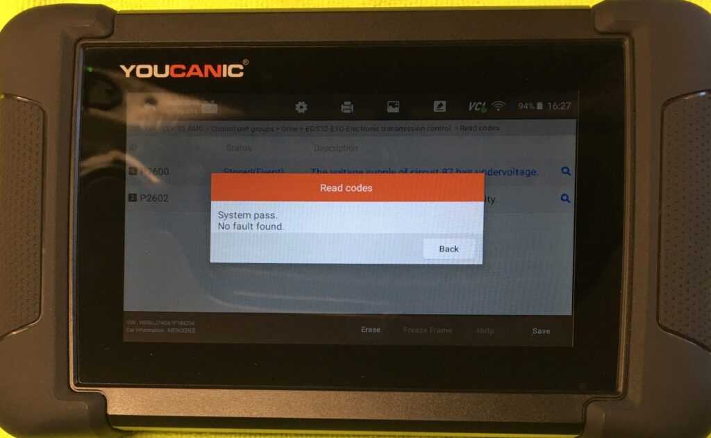
The scanner is Wi-Fi and Bluetooth capable, which has worked flawlessly, allowing access to my home network which facilitated printing or emailing reports directly from the UCAN. After I added the Mercedes by entering the VIN, I scanned all the modules and the UCAN confirmed what was suspected… very likely the conductor plate sitting atop the valve body was the culprit. That same independent repair shop estimated $2,000 for the fix. NOPE. I can do this.
UCAN main screenHere is the key piece of the puzzle, allowing me to confirm the diagnosisP2101 was the DTC and this was ChatGPT about it
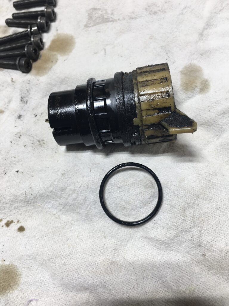
It is possible that simply replacing the connector that plugs into the 722.6 Tiptronic transmission would have fixed my problems, for a fraction of what I paid for the conductor plate kit and fluid. And ChatGPT provided a detailed method for testing it. However, with all those miles on my CLK I decided to purchase the kit. I went to AutohausAZ for the Febi kit and seven liters of Fuchs Titan 4134 ATF, which set me back $355 and change.
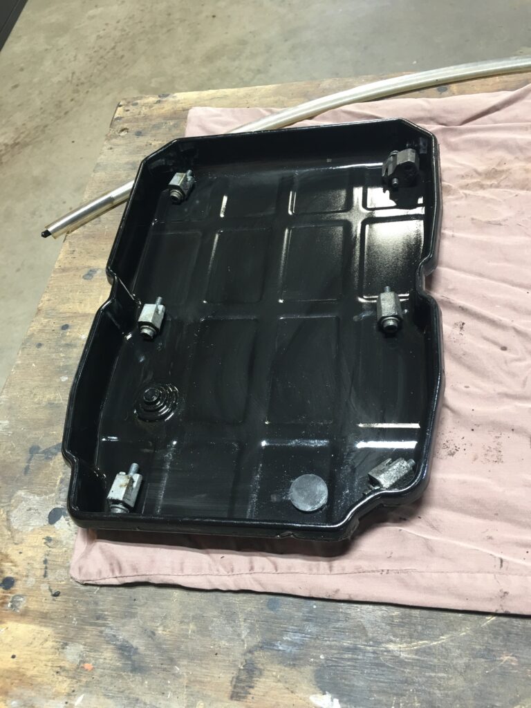
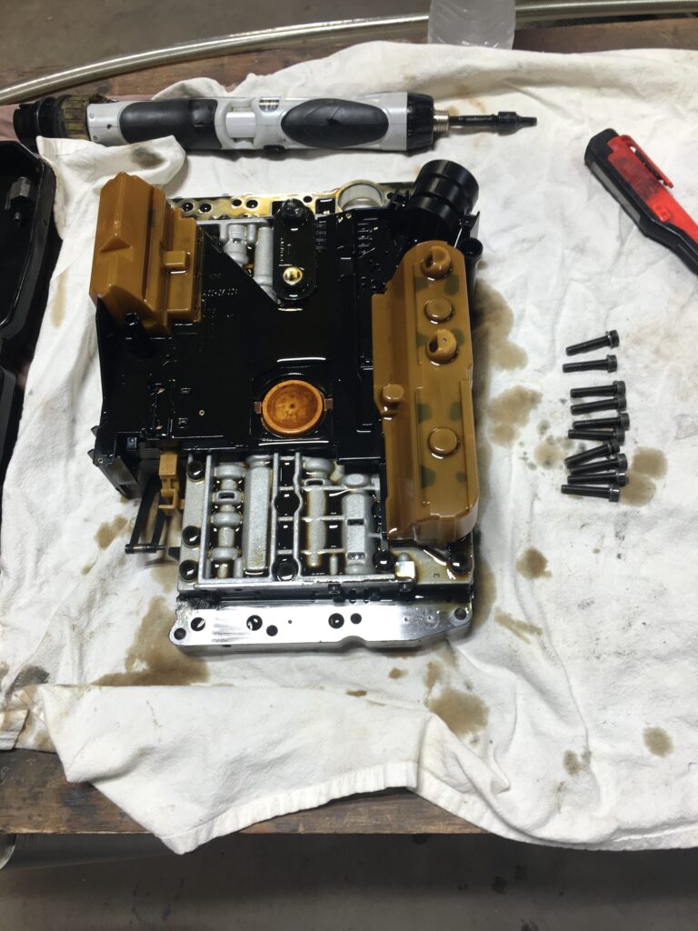
Out with the old ATFPan cleaned up, magnet in lower right.Remove the connector’s 7 mm bolt, using a wobbly extension.The oil covering the connector tells the story… leaking o-ring equals faulty electrical connection to the transmissionThe valve body and conductor plate on the bench
The Barn has a two post lift, which made the job much more comfortable. It is not a difficult job, just a bit messy with the fluid. Have your bag of kitty litter handy to soak it all up. I recommend letting the car cool down before diving into the job, since the exhaust and the transmission itself can be uncomfortably hot. If I had to do the job a second time, with the advantage of the lift and the experience, I’m guessing I could do it inside 90 minutes once the car is positioned.
Arrow indicates front of vehicle, the blue marks show the ten bolts that fasten the valve body to the transmissionSince I was solo on this job, I used our trans jack to hoist the valve body. The box was used to support the valve body while I started a couple bolts Not only is the valve body assembly a bit heavy, using the transmission jack let me make sure that the shifter linkage was positioned correctly.
WARNINGS:
The torque spec for the pan attaching bolts was something like 71 inch/pounds. I proceeded to do it in stages and when I torqued to 40 inch/pounds one of the bolts stripped! Fortunately I found a slightly longer bolt of the same spec and was able to put a nut on it, as the holes go all the way through the transmission flange.
When I finished the job and lowered the car, a warning light began blinking – in my brain. At the start of the job I opened the trunk and disconnected the ground from the battery. THEN I SHUT THE TRUNK… don’t do that! Panic set in because the last time I was in this situation (dead battery, trunk closed, utterly useless physical key in the fob) I had to crawl into the trunk and disassemble the latch. This time, being a couple years older and smarter, I hooked a battery charger up to the charging connections under the hood, set the charger on something like 45 amp/start setting and my key fob trunk button worked! Phew.
Last caveat… when I refilled the transmission, I added 4 liters of ATF per instructions. I thought I had a reading on the dipstick – yes that long snaky one – that indicated fluid level was fine. However, on the following day it did the limp home mode, stuck in 2nd gear. After letting the car sit for an hour while I visited my doctor, I made it home with the transmission working like it should. I investigated.
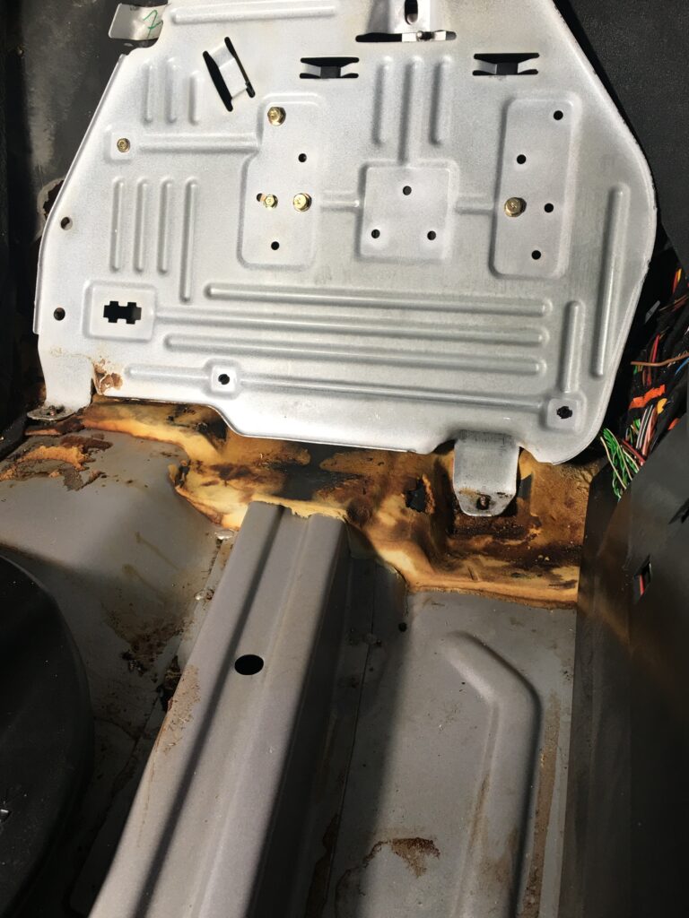
Under the passenger footwell carpetThe TCM is on the right.The CLK55 AMG transmission control module
There was advice out there suggesting that perhaps the fluid leaking past the failed o-ring on the connector at the transmission had wicked up to the connector at the TCM. But it was dry as a bone.
I decided to check the fluid level again. Warmed up to 80 degrees C, shifted through the gears while idling in the garage, then a short drive around the neighborhood, and back to the garage to measure again. I was at least 1.5 liters low. With great(er) care I filled to the mark. Took it for a long drive and then I hooked up the UCAN scanner, cleared the codes, read the transmission module again and success!
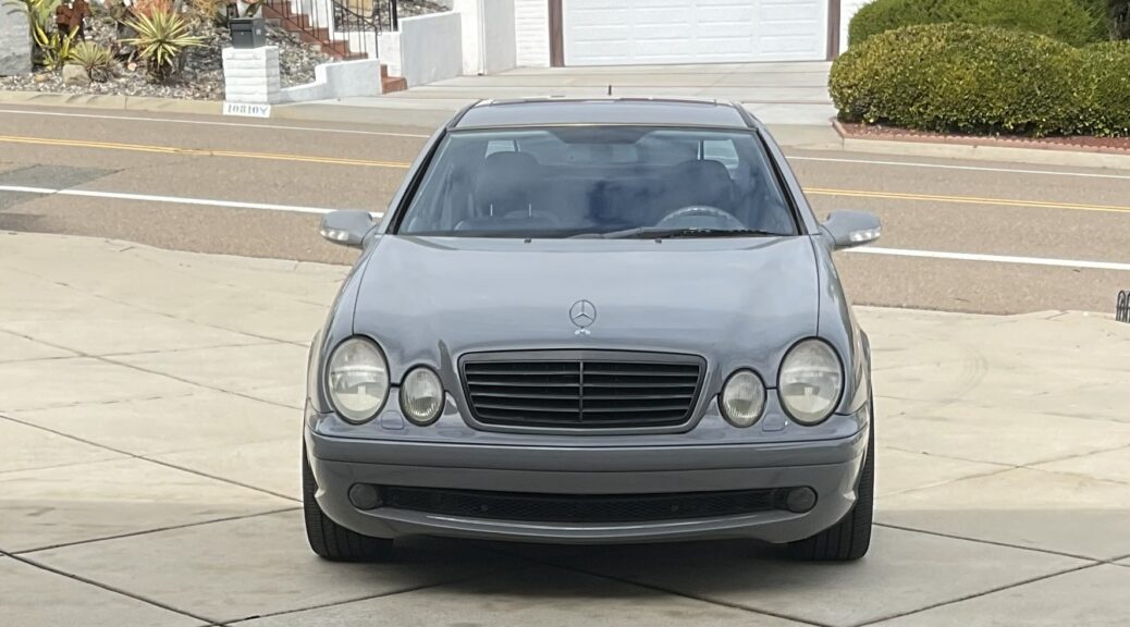
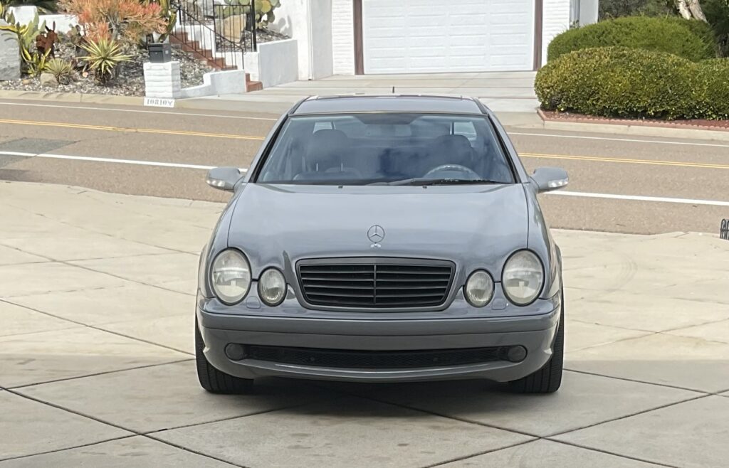
Since then the CLK has been flawless. It’s showing 185,000 miles on the odometer, short of my quarter million milestone, and with my limited driving these days, maybe the “next guy” will get there. It is such a great car… gentleman’s hotrod from an era when the technology was just about right, for me.
At job conclusion, this is what I was hoping to see!On the road again
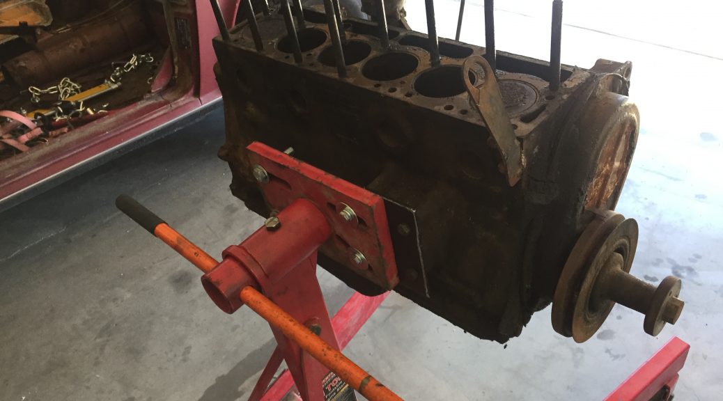
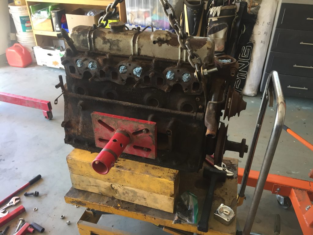
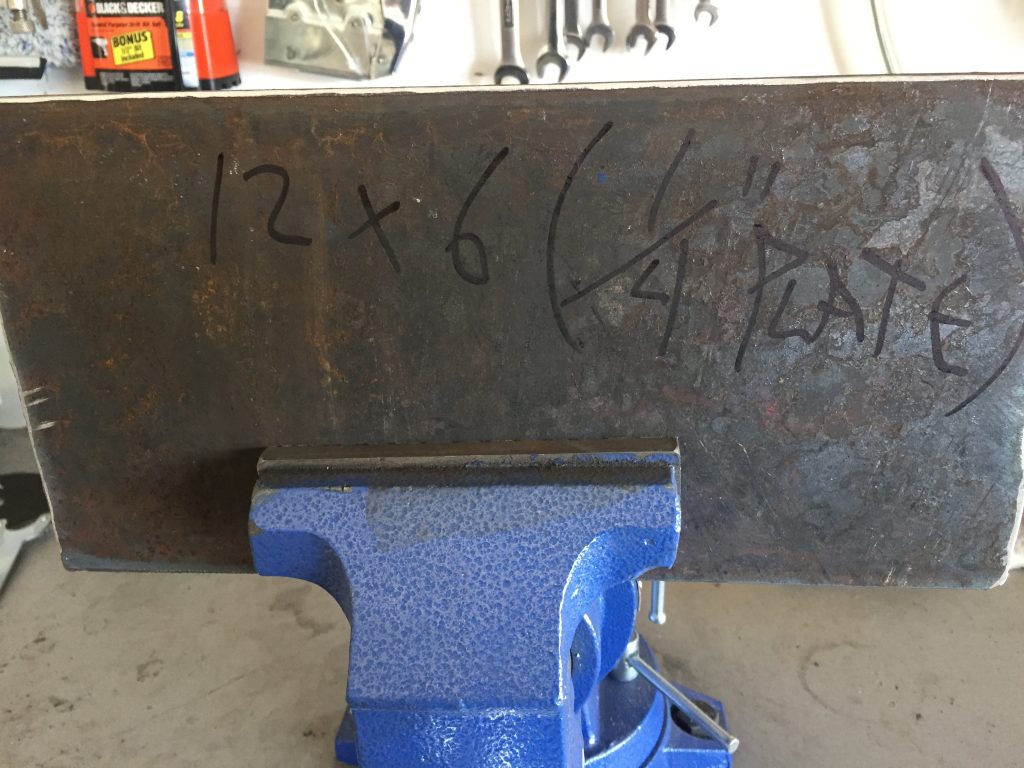
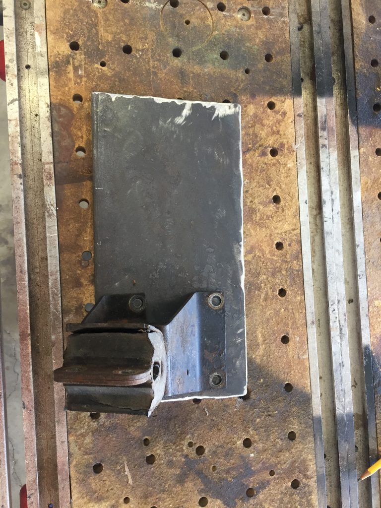
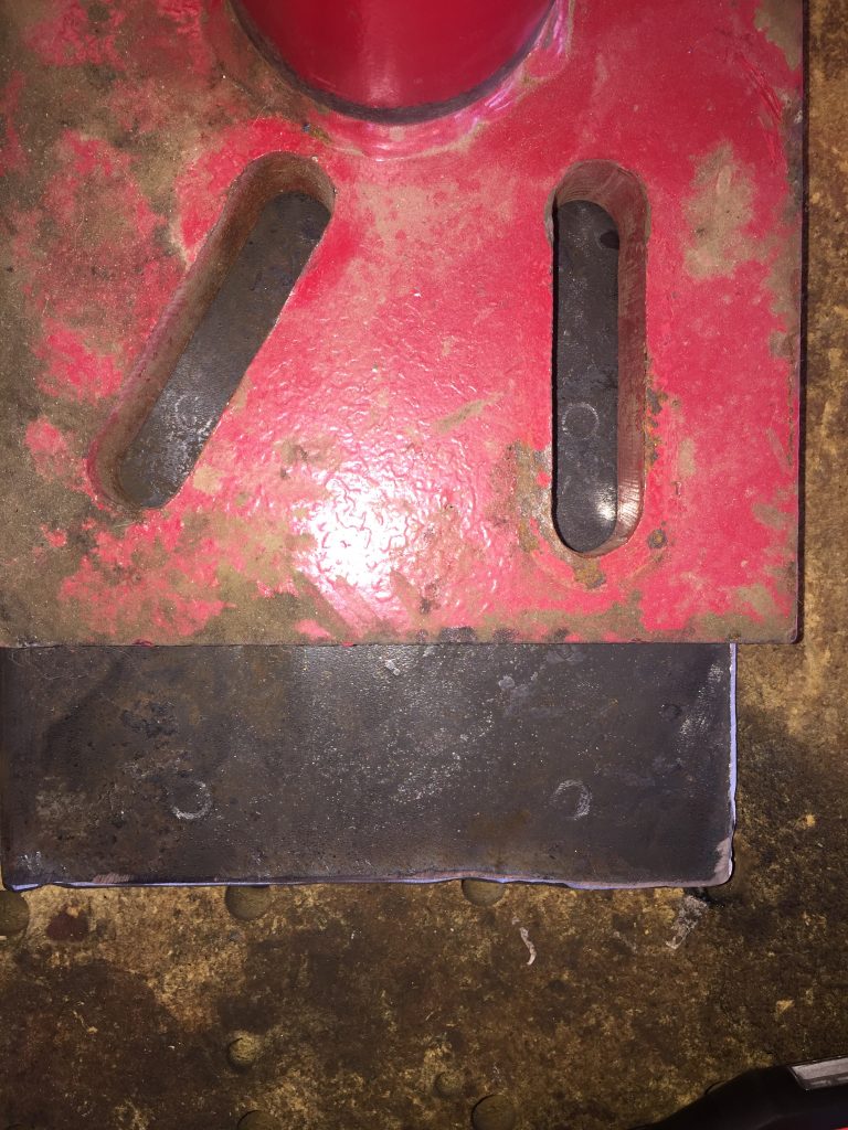
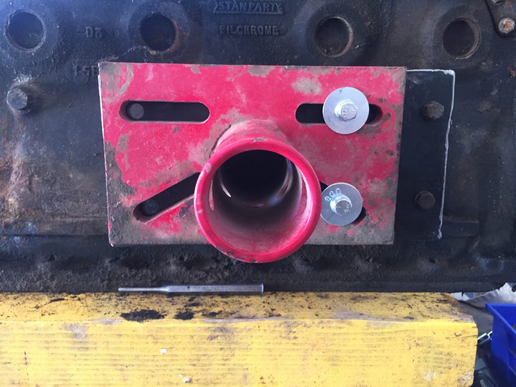
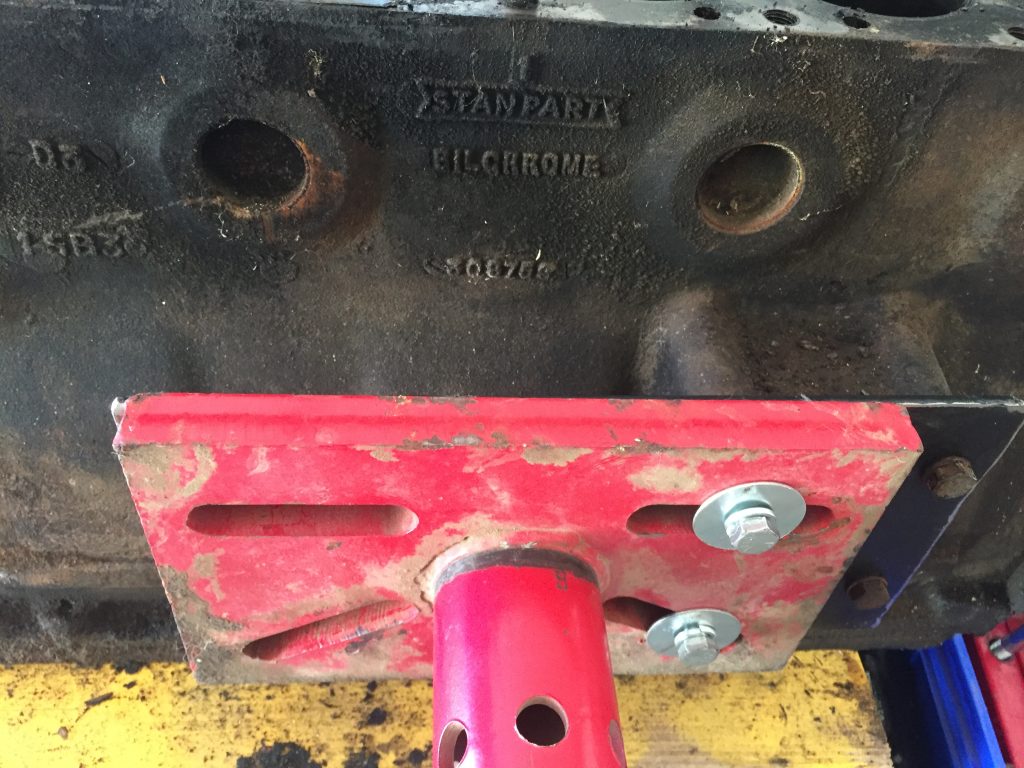
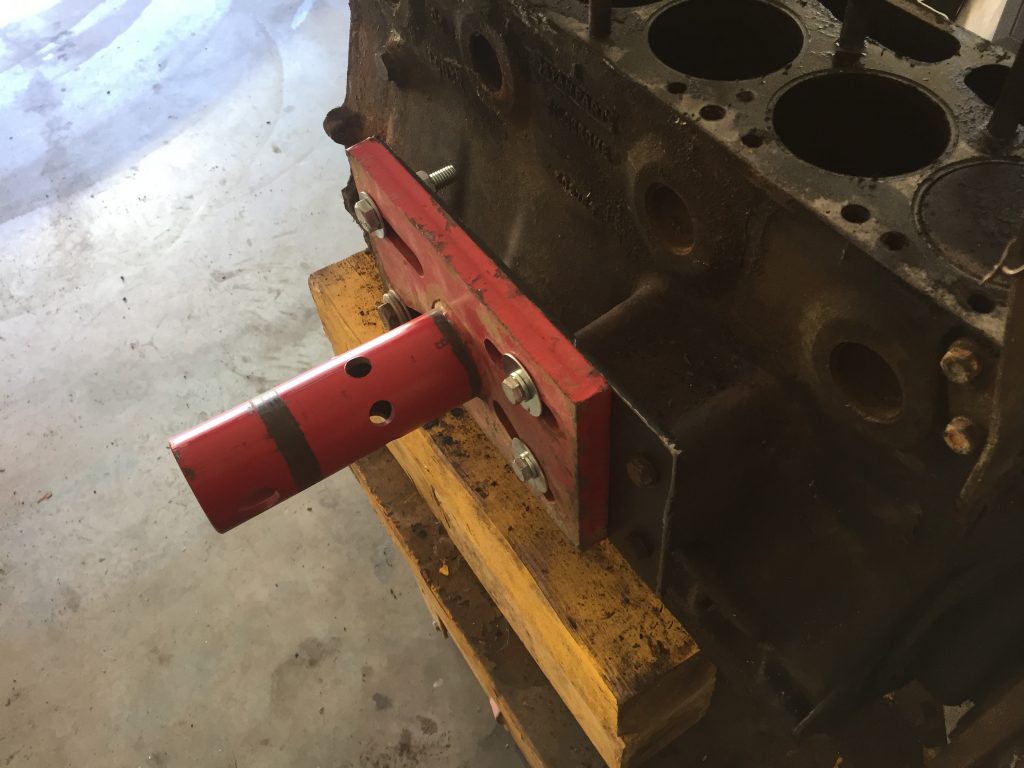
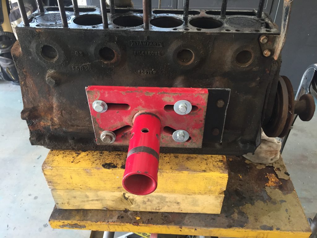
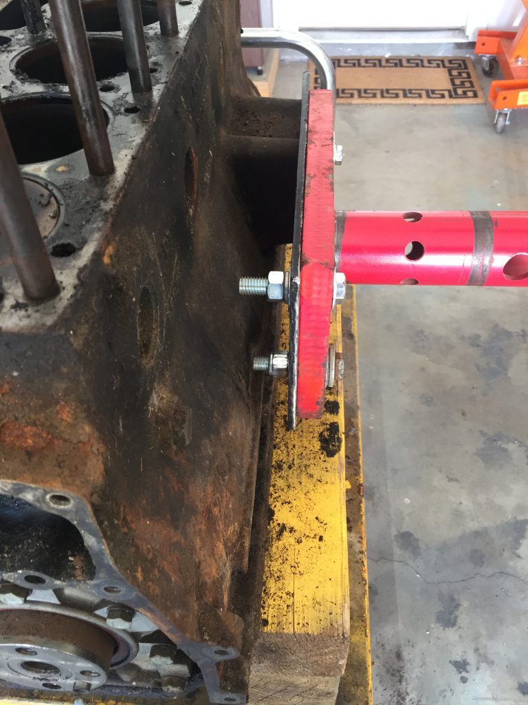
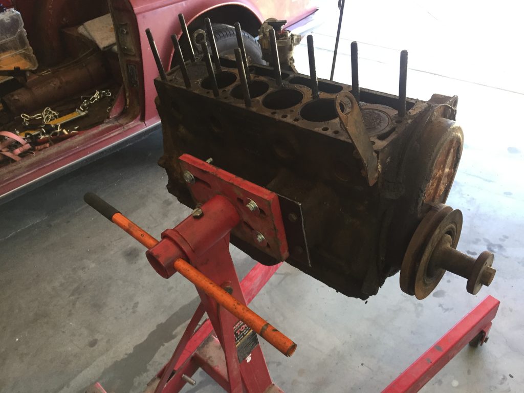
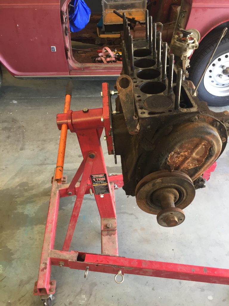
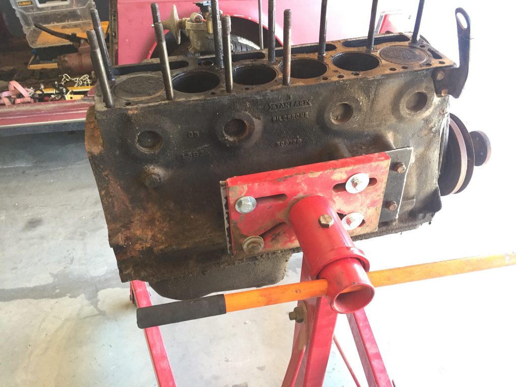
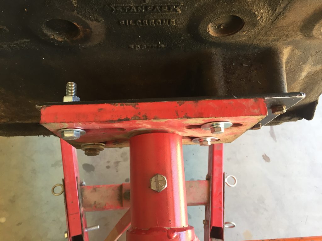
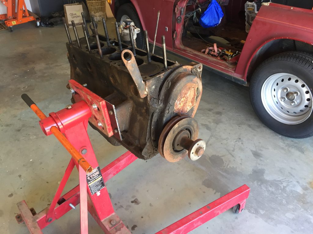
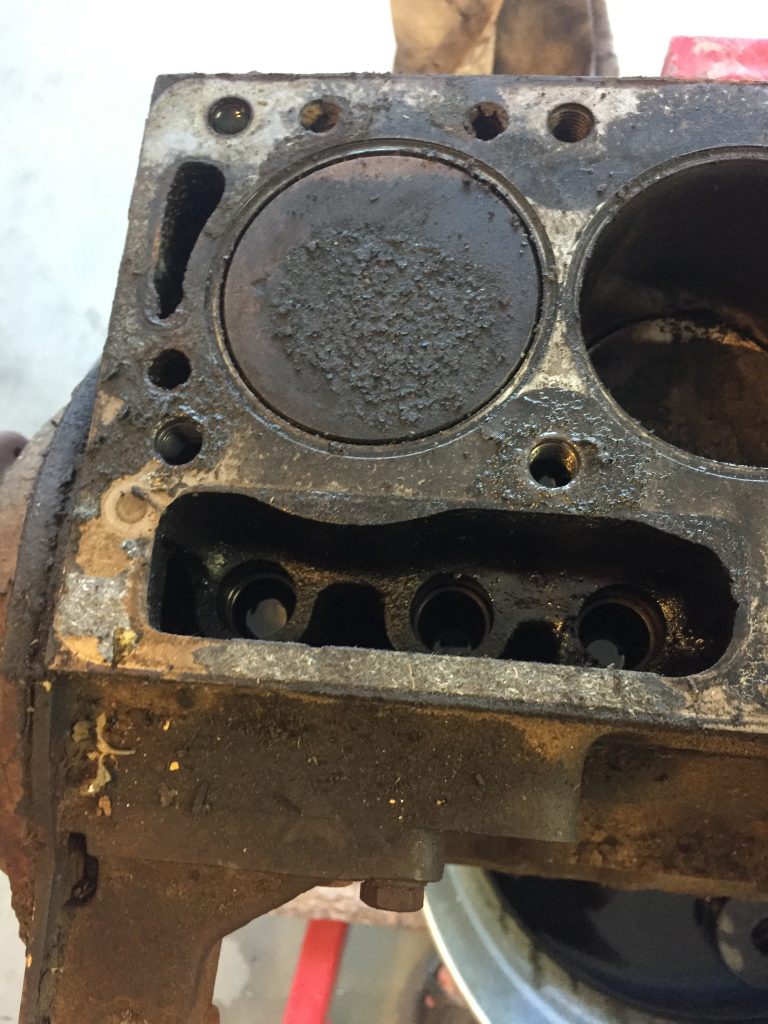
Will this work?1/4 plate was beefy enoughEngine mount used as a template for holesYep it works, easy to rotate the engineSide mount worked out well for the TR6Piston tops and cylinders looked decent
The other engines I’ve rebuilt were always mounted onto the stand at the rear of the block. After reading what other TR6 owners had done, I chose the side mount. This worked out very well, and the 12″x6″ quarter inch thick plate was plenty strong… no flexing or movement at all.
When the 1956 Chevy farm truck entered the barn in January, it was running pretty well. Vacuum at the intake manifold was at 20 inches and a compression check – wet and dry – showed even numbers across the cylinders. After pulling the engine we did a leak down check and again the numbers were similar for all the cylinders, even if percentages were a bit high. We could hear air escaping through the crankcase breather pipe, indicating the rings weren’t sealing as well as they might. But that check was with a cold engine, so we decided against a rebuild at this time.
We cleaned and painted the engine, rebuilt the carburetor, installed new spark plugs, set the valve lash and static ignition timing, and then added a power steering pump and alternator.
The 235 six, with fresh paint and added power steering pump and alternator.
We went full quick and easy mode to fire up the engine and check for leaks, using the engine stand as our test bed.
Our engine test bed worked like a charm, simple and easy.
We hooked up our two essential gauges – oil pressure and vacuum – and fired up the stovebolt six. And it ran like crap. Would not idle, vacuum below ten inches, ignition timing out in left field just to get it to run. We grabbed the aerosol can of carburetor cleaner for a squirt around the base of the Rochester and immediately the RPM increased. Bingo: a vacuum leak. No problem, easy fix, right?
We tried every combination of gasket, no gasket, Loctite 518 with gaskets, 518 without gaskets, thick gaskets, thin gaskets… no improvement. We used our flat metal welding table and 600 grit wet/dry paper on both sides of the insulator, and on the carburetor base until we were sure they were flat. Still no improvement.
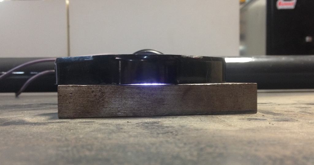
Finally getting smart, we brought out a flat chunk of metal that we keep in the toolbox and laid the insulator on it with a flashlight behind.
Valuable diagnostic tools: a flashlight and a flat piece of metal.
Light seen shining under carb insulator, showing warpage.
The insulator was clearly warped. We installed a new (nine dollar) insulator from Classic Parts of America, and, after doing a static ignition timing reset, put it all back together for the umpteenth time, and… eureka! The old six purred like a kitten and once again showed an excellent vacuum reading.
As you can see, Lance is excited… the engine is purring and he’s holding a Corona. We used a thick gasket between the insulator and manifold, but applied minimal torque on the bolts attaching the carburetor to the manifold. I may disassemble one more time and pitch the bottom gasket as I suspect it was a contributing factor with just two bolts holding down the Rochester 1 barrel.
So, we bought the ’59 Apache. Generally, we knew what we were getting, but what exactly did we buy? Time for a little detective work.
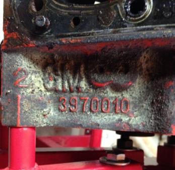
It has a 350 small block Chevy engine. The number at the rear of the block on the driver side tells us that this is a 3970010 block casting, which had a ten year run, from 1969 to 1979, and was used for 302 and 350 cubic inch engines.
Rear of block, driver’s side.
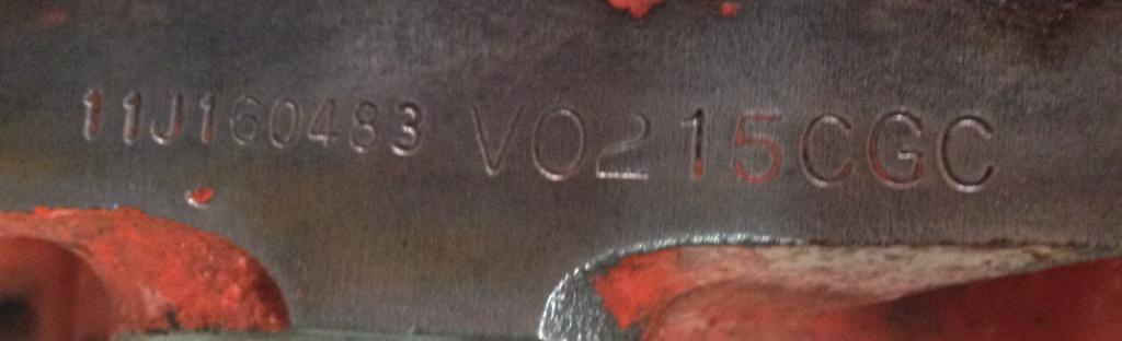
To get a little more specific information, we looked for the engine’s three letter suffix, in our case “CGC,” found on the passenger side of the engine just below the cylinder head at the front. Turns out our engine was 350 from 1971 with 245 hp. It would have been installed in an El Camino with the turbo-hydramatic, or a full-size manual transmission car, police car, or taxi.
Front of block, passenger side.
The “11J” at the beginning indicates the car was a Chevrolet, model year 1971, built at GM’s oldest assembly plant in Janesville, Wisconsin (set up in 1919, and shuttered in 2009). The beginning of the engine code “V0215” indicates the engine build was at the Flint plant on February 15th.
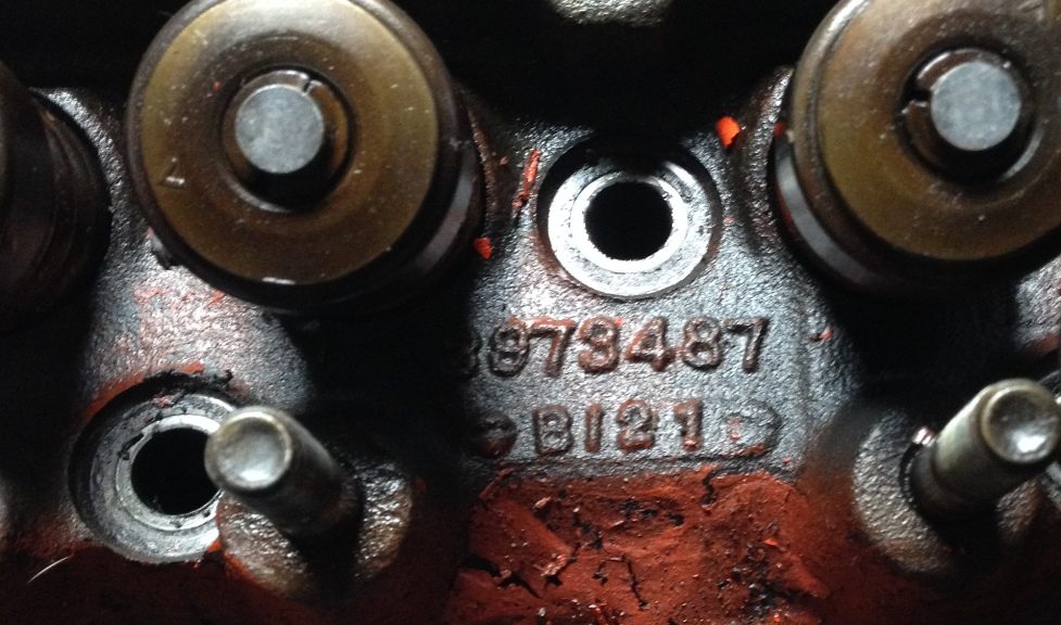
Under the valve cover.
Removing the valve covers revealed the cylinder head identifying numbers “3973487” which indicates that this is a “smog” head with 1.94 intake / 1.50 exhaust valve diameters. Not a good base for making power because of the size (76 cc) and shape of the combustion chambers. We ended up swapping these heads for ones with a 58 cc combustion chamber, just to put a little more pop in the explosion… more on that in a future post about the engine rebuild.
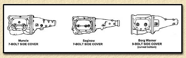
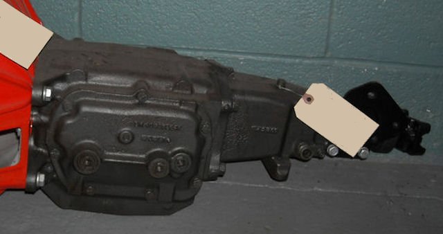
It was easy to identify the transmission as a Saginaw. These manual gearboxes have seven bolts fastening the side cover and all three shift levers are on the side cover. The Muncie also has seven bolts securing the side cover but the reverse shift lever is on the tail housing.
photo from http://chevellestuff.net/qd/muncie.htm
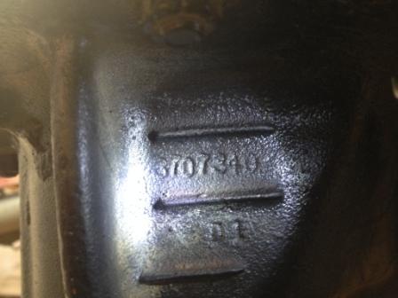
The final piece of the drivetrain – the differential – yielded its specifications, as well, once we were able to guess correctly at the last digit of the casting number.
A Google search on GM differential 3707340 pointed us to a number of gear vendors. They revealed the same information…
GM ’55 – ’64 1/2 ton truck
drop out carrier
10 bolt rear cover
c/clip axles
12 ring gear bolts (3/8 x 24)
ring gear diameter: 9.375″
pinion nut size 1 – 1/8th”
Yukon Gear, Randy’s Worldwide, and Sierra Gear all list a GM55T-338 replacement ring and pinion with a 3.38 to 1 ratio along with all the other parts necessary for a rebuild. I would choose that ratio over the Apache’s, which seems to be a 3.90 ratio. In fact, I’d like to go even further via an overdrive transmission. If I could find a three-speed Saginaw with overdrive – for a reasonable price – I would swap it for the four speed in a heartbeat.
But first things first. Unfortunately, the Apache’s rear end is making the worn-ring-and-pinion howl and that means I need to put it on the bench for inspection and adjustment or replacement.
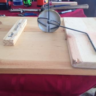
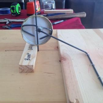
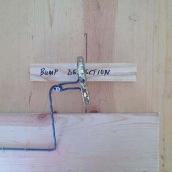
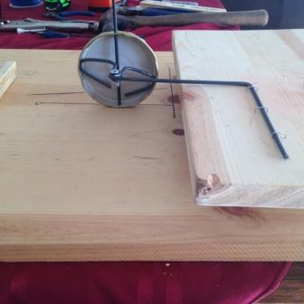
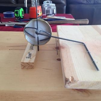
Why a post about bump steer? Well, because we’ve built two trucks and both suffered from horrendous bump steer problems. One was brought on by the installation of a drop axle, and the other by upgrading to later GM power steering setup.
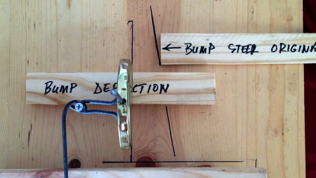
How to make it livable? You need to get the drag link parallel with the ground. A short drag link that is steeply inclined could see you bouncing into a ditch or into the oncoming lane. Not knowing how significant the effect might be, I built a simple model.
If you start with a steeply inclined drag link,
and hit a bump,
you get a lot of steering effect.
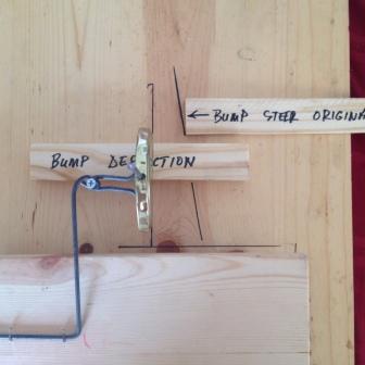
If you start with a more level drag link,
and you hit the same bump,
you get negligible bump steer. Compare to the original bump steer line.
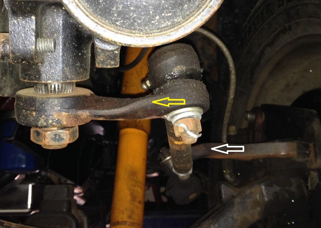
The ’48 Chevy had a CPP kit which facilitates an upgrade to a 1967-89 Chevy truck power steering setup . This entails mounting the steering box to the outside of the frame rail. CPP sells a Pitman arm for lowered trucks that allows the drag link to be dropped in from above the Pitman arm. In addition, we fired up the oxy-acetylene torch and bent the both the Pitman arm (yellow arrow) and the steering arm (white arrow) to achieve a horizontal drag link when the car was sitting on the ground. This picture was taken with the ’48 on the lift so the drag link is at a slight angle in this photo. It took a couple tries, but we finally made the steering manageable.
The twist in the Pitman arm is to prevent binding at extreme bump or extension angles.
Since this truck has significant body roll, especially at the front end, at some point we will source an anti-roll bar. (We hope) that will further decrease the bump steer effect and make the truck a little more sporty in the corners.
Doing this hot rod building and restoration stuff, either as a hobby or as a business, is so rewarding because it’s a creative endeavor. You’re bringing a vision that exists in your mind, through a planning stage and, finally, to a real physical product. As a Taoist might say, moving something from its Yin aspect to its Yang aspect.
But, damn… there’s always something. Especially when the creative process starts with a car or truck that is half a century old. There will be blood. And frustration. Rarely is anything simple and straightforward. Not complaining, mind you, problem solving is part of the fun. So with that in mind, we’ll share some solutions that might apply to your project as well as ours.
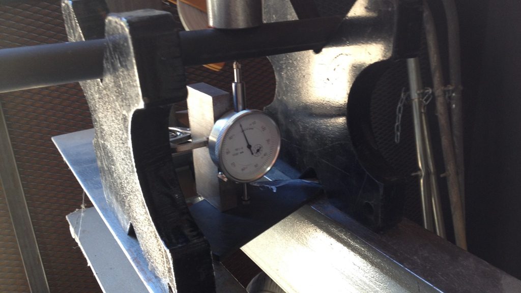
Even tools can cause headaches. Trying to straighten the HF bead roller shaft, which had a wobble in it.